61780 0221
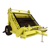
CHAIN CASE The conveyor belt is driven by the hydraulic motor which transfers
power to the drive chain and the drive sprockets located inside the chain case.
Drive chain should be adjusted so that there is approximately 1/4"(6.35mm) slack
but no more than 1"(25.4mm) slack midpoint between the sprockets. Adjustment
is made by loosening the two bolts that fasten the motor mount to the front tank
motor bracket and tightening the adjusting bolt, which will move the motor and
attached front sprocket assembly forward. Replace chain when adequate
adjustment can no longer be achieved. Note: Chain tension should be ¼”
minimum (6.35 mm) and 1” maximum (25.4 mm).
BUCKET The bucket catches the debris the conveyor belt picks up. When full, the bucket is raised and then
tripped, pivoting on the lift arm and bucket bearings. There is a bucket stop on the left side, which stops the
bucket at its dumping position and prevents the bucket from spinning and over turning. There is a block on
either side of the bucket which nests into the angled guides on each side of the bucket on the frame. When
the bucket is in its correct position, the blocks should be to the bottom of the guides and slightly off the
frame.
BUCKET LIFTING MECHANISM The lift arms attach the bucket to the frame. They are elevated
hydraulically by the two larger lifting cylinders. They lift the bucket back/away from the frame for emptying the
collected debris. The lift arms are supported by a sleeve bearing located at the top of the side frame on each
side of the Surf Rake
®
. The grease port on top of the side frames should be greased weekly to prevent the
sleeve bearings from freezing up.
BUCKET TRIPPING MECHANISM After the bucket is raised, it is tripped to empty the collected debris. It is
tripped by the smaller pair of dumping cylinders, dumping sprockets and turnbuckle assemblies. After the
bucket is tripped and emptied of debris, it must be un-tripped before it is lowered.
BUCKET GUIDES The guides are located on the frame on either side of the bucket and should be used to
position the bucket correctly by tightening or loosening the dump chains. If the bucket chain assemblies are
loose when they are down, the turnbuckles should be tightened until the chain assemblies are both taut and
lifting the bucket blocks slightly off of the frame. This adjustment should be done when the bucket is empty.
If the bucket blocks are not nested near the bottom of the guides, the dump chains are too tight. The
turnbuckles must be loosened until the chain assemblies are both taut and lifting the bucket blocks slightly
off of the frame.
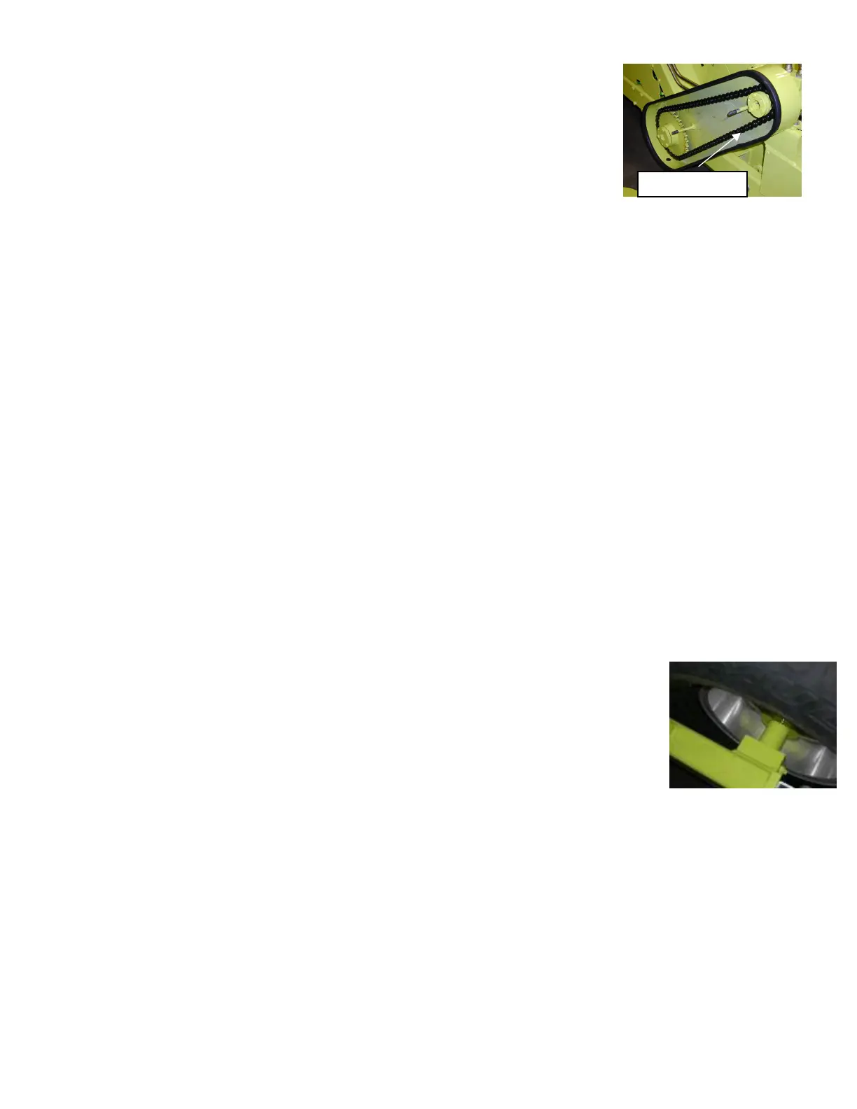
HUB ASSEMBLY, WHEEL AND TIRE The two hub assemblies are attached to the frame
by the spindle. The hub rides on two races and bearings that can be adjusted as they
wear with the adjusting castle nut and pin. There is a refillable grease reservoir on each
hub that maintains pressure to the bearings.
Torque the lugs on the wheel and tire assemblies to 95 ft/lbs. The tires are inflated to 18
PSI. It is important that both tires be the same pressure.
AUTOMATIC FINISHER (OPTION) The grooming finisher is attached to the rear of the Surf Rake
®
to
smooth the clean sand and eliminate tire marks left by the tractor and beach cleaner.
HYDRAULIC COMPONENTS (CONVEYOR)
The conveyor hydraulic system is separate from the bucket or finisher hydraulic systems. It is a closed
system made of the following components:
A reservoir of hydraulic fluid on the front of the Surf Rake
®
A hydraulic pump, attached to and powered by the tractor PTO, which circulates the hydraulic fluid
The flow control, which regulates the flow of the hydraulic fluid through the motor
The conveyor belt motor that turns the chain case drive chain and sprockets and turns the conveyor
The hydraulic fluid is then filtered and returns back to the Surf Rake
®
reservoir.
CHAIN TENSION