Manual 2100-614K
Page 5 of 61
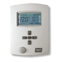
A secondary sensor is located internally on the main
controller board and serves as a reference and back-up
sensor to the local sensor. If the difference between the
two sensors is less than the differential setpoint, the local
sensor will be used as the controller's temperature point
of reference. The differential is adjustable from 12-20°F.
12°F is the default setting. If the difference between the
two sensors is greater than the differential set-point, then
the controller will check to determine if the on-board
sensor is reading a temperature that is between the SP
(set-point), plus the differential and the SP minus the DB
(dead-band) minus the differential. If it is, the on-board
sensor will become the valid sensor reading and the
controller will ignore the local sensor reading. If not, then
the controller, will still use the local sensor reading. This is
to add additional levels of operational capability in the rare
event the local sensor fails. If the controller is operating in
this mode, it is indicated by the lower left decimal point
ashing in the display. If this feature is not desired, set the
differential set-point to OFF. This disables the on-board
sensor. This may be necessary if the controller is located
in one room and the local sensor has been relocated to a
different room. NOTE: For purposes of testing when the
local sensor is manually driven higher or lower by applying
warm or cool water to the probe the on-board sensor is
inhibited for the first 30-minutes following power up, or
when power is cycled off and back on.
The controller is designed to accept 1 or 2 additional
sensors and those have 35-foot leads. The Bard part
number for the optional sensor with 35-foot leads is
8612-023A. These can be installed as required in the
structure to address hot spots, barriers to airow, etc. If a
remote sensor(s) is used, the on-board sensor is disabled.
The local sensor remains active.
It is recommended that the sensor lead wires be installed
in conduit for protective purposes.
TEMPERATURE SENSOR LOGIC
The standard local (LSEn) sensor monitors the temperature
at the controller location. If this is the only sensor
connected, it will control the temperature read-out, the
space (building) temperature, and also be used for Low and
High Temperature alarm functions.
If one or more REMOTE sensors are installed and
connected (Rem 1 or Rem 2), the temperature read-out
will display
and the building will be controlled to an
average of all connected sensors. If there is more than
10F difference from the highest to the lowest connected
sensor, the actual control will be governed by the hottest
sensor for cooling and the coldest sensor for heating.
If alarm boards are utilized, the highest reading of any
connected sensor will be used for high temperature
alarm and the lowest reading sensor will be used for low
temperature alarm. The on-board sensor is ignored if two
(2) or more sensors are connected to the Local, Rem 1
or Rem 2 sensor inputs.
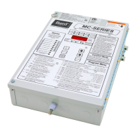
BASIC MC4002 CONTROLLER
INPUT/OUTPUT SPECIFICATIONS
MC4002 Controller Connections
Located on Main Controller Board
Unit #1 C – 24VAC common
R – 24VAC hot
G – fan (Form A, NO)
Y1 – 1
st
-stage cool (Form A, NO)
Y2 – 2
nd
-stage cool (Form A, NO)
W – heat (Form A, NO)
Unit #2 C – 24VAC common
R – 24VAC hot
G – fan (Form A, NO)
Y1 – 1
st
-stage cool (Form A, NO)
Y2 – 2
nd
-stage cool (Form A, NO)
W – heat (Form A, NO)
F1-F2 Fire/smoke interface
Shipped with jumper installed (a)
48Vdc Back-up power input
-24Vdc or –48Vdc
-20V to –56V range
Local Main sensor, 12-inch leads
CU – copper, AG – silver
Polarity sensitive
Rem 1 Optional remote indoor sensor
CU – copper, AG – silver
Polarity sensitive
Rem 2 Optional remote indoor sensor
CU – copper, AG – silver
Polarity sensitive
Gen Generator interface G1-G2
Shipped with jumper installed (a)
H1-H2 Humidity controller input
Requires optional controller
Field installed
(a) These connections require either jumper or Normally
Closed (NC) relay contact at the Fire/Smoke and
Generator interface for Controller to function.
NOTE: All alarm and output relays are dry contacts
rated 1A @ 24 VAC.
NOTE: All alarm relay outputs have 10-second delay
before issuing to protect against nuisance alarm
signals.
NOTE: All sensors are polarity sensitive. The copper
lead must connect to terminal CU, and the silver
lead to AG. Sensors are solid state, not RTD. Use
only sensors supplied by Bard. Sensor leads can
be extended up to 200 feet. Use 18-gauge twisted
pair with soldered connections.
NOTE:
Sensors are
solid state,
not RTD.
Use Bard
sensors only.