Manual 2100-559A
Page 3 of 6
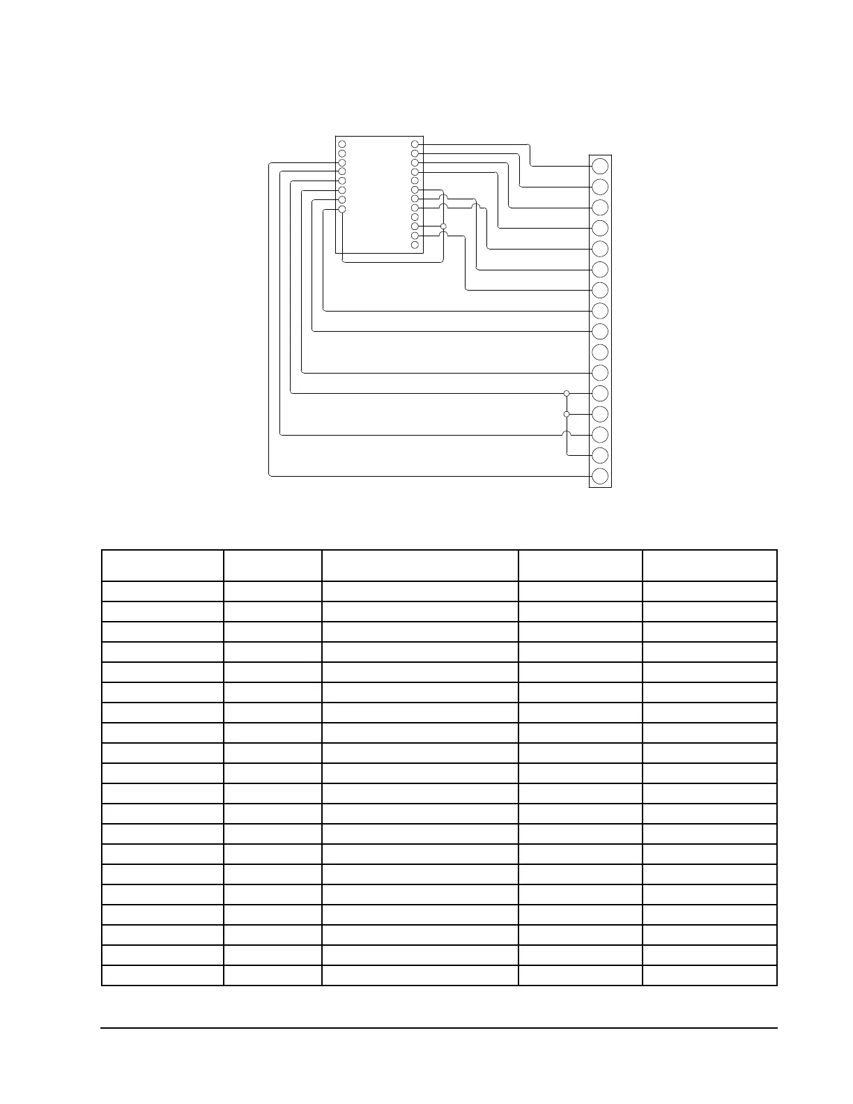
Table 1
Controller Connections
Figure 1
Control Wiring
C
5
3
1
6
4
R
7
BLOCK
F
E
Y1
G
W1
W2
Y
UNIT LOW
VOLTAGE
TERMINAL
2
IN3
IN4
-A
+B
24V~/R
24 COM
IN2
GND
OUT 9
GND 7-9
OUT 8
OUT 7
RLY 6
SC 4-6
RLY 5
RLY 4
RLY 3
SC 1-3
RLY 2
RLY 1
MIS-2852 C
8403-066 DIGITAL
CONTROLLER
Control Terminal Unit Terminal Function Type Form
+B -- MSTP + (Not Used) Communications --
-A -- MSTP - (Not Used) Communications --
IN4 7 Outdoor Temperature Sensor Input 10K Ohm Type 3
IN3 5 Pressure Transducer Input 0-5 VDC, 0-700PSIG
GND 3,4,6 Sensor Grounds Input 2-10 VDC
IN2 2 Lockout Alarm Input Relay Closure
1
24 COM C 24VAC COM Power 24 VAC
24V~R R 24VAC Power 24 VAC
OUT 9 F Fan Motor Control Analog Output 2-10 VDC
GND7-9 E Control Guard Analog Output 2-10 VDC
OUT 8 Y1 Unloader Solenoid Control Analog Output 0 or 5 VDC PWM
2
OUT 7 G Blower Motor Control Analog Output 2-10 VDC
RLY 4 W1 Heater Contactor #1 Relay Output Relay 24 VAC
SC4-6 Jump to 24V 24VAC to Relay Outputs 4-6 Power 24 VAC
RLY 5 W2 Heater Contactor #2 Relay Output Relay 24 VAC
RLY 6 -- Not Used -- --
RLY 3 -- Not Used -- --
SC1-3 Jump to 24V 24VAC to Relay Outputs 1-3 Power 24 VAC
RLY2 Y Compressor Contactor Relay Output Relay 24 VAC
RLY 1 Not Used --
1
Open relay contacts 3 VDC, closed contacts 0 VDC
2
Pulse Width Modulation
Field-Installed Jumper
Field-Installed Jumper
MIS-2852C
 Loading...