Manual 2100-365
Page 45
34. REFRIGERANT CHARGE
The correct system R-22 charge is shown on the unit
rating plate. Optimum unit performance will occur
with a refrigerant charge resulting in a suction line
temperature (6” from compressor) as shown in
Table 18.
The suction line temperatures in Table 18 are based
upon 80 degrees F dry bulb / 67 degree wet bulb (50%
R.H.) temperature and rated airflow across the
evaporator during cooling cycle.
Total system charge for these models can be found in
Table 1.
35. FAN BLADE SETTING DIMENSIONS
Shown in Figure 21 is the correct fan blade setting
dimension for proper air delivery across the outdoor
coil.
ledoM
noisnemiD
A
42GW1
03GW1
63GW1
24GW1
84GW1
06GW1
TABLE 19
FAN BLADE DIMENSION
FIGURE 21
FAN BLADE
A
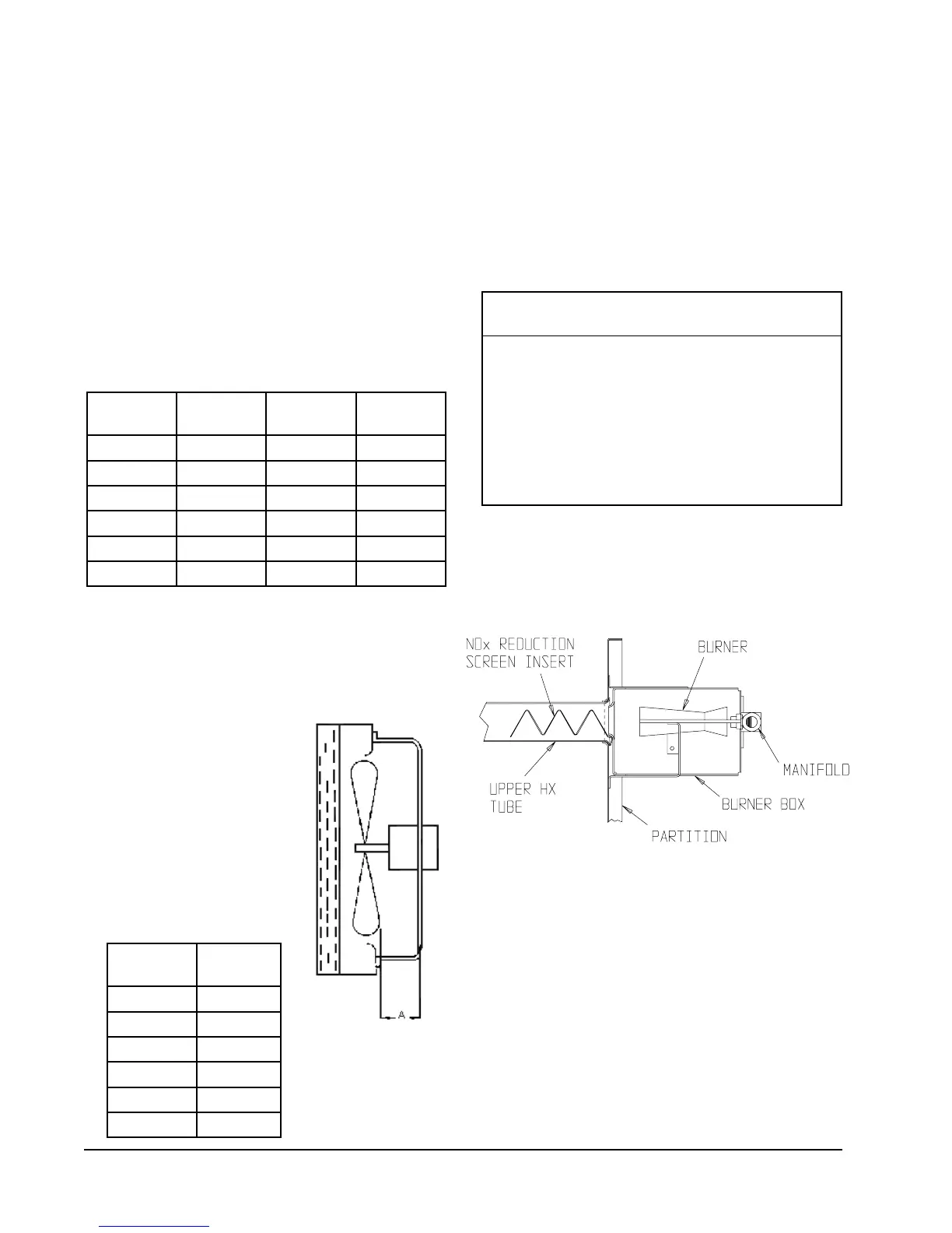
36. LOW-NOX BURNER ASSEMBLY “N”
SUFFIX MODELS ONLY – U.S.
INSTALLATIONS ONLY
NATURAL GAS MODELS ONLY
Model numbers designated with an “N” are designed
for low NOx emissions which comply with all
California Air Quality Management District
regulations for nitrogen oxide emission levels. Refer
to Figure 22 for NOx insert information.
* *
IMPORTANT
* *
For propane (LP) conversions the NOx
reduction screen inserts shown below must be
removed. This is accomplished by removing
the burner box assembly and removing the
NOx screens. Reassemble unit properly
before firing. Failure to remove the NOx
screens can result in improper operation and
malfunction of the burner system.
FIGURE 22
LOW NOX INSERT
MIS-1481
TABLE 18
REFRIGERANT CHARGE
ledoM
detaR
wolfriA
F.geD59
.pmeTDO
F.geD28
.pmeTDO
142GW00895-1526-06
103GW000106-8526-06
163GW001195-6526-06
224GW003175-5586-66
184GW055165-4566-46
106GW056185-6586-66