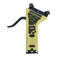
CT12A INSTRUCTION MANUAL
56-101-03100-E CH. 3
May
/ 29 / 09 Page 13 of 19
Only for multi-cable units, by keeping BKLITE / CABLE SEL button pressed down for
more time than it is required to turn backlight on and off, the user can select the cable size,
as it is explained in section 6.
6. SETUP OF CT12A FOR TAKING TENSION MEASUREMENTS
The preparation for taking tension measurements depends on the CT12A configuration.
If the CT12A to be used is of the single-cable type (as described in Section 1):
y Determine the cable size. If needed, use cable gauge provided at one end of the CT12A.
y Check the CT12A label and make sure the listed cable diameter matches the cable size.
y Verify that the number engraved in the risers match the number listed on the CT12A label.
y Press the ON / OFF button to turn CT12A on. The introductory display described in Sec-
tion 2 will be shown.
y If current settings are not appropriate, select desired Operation (standard or averaging)
and temperature (°F or °C) modes, following the steps indicated in sections 3 and 4, re-
spectively, immediately after power on.
y After these settings are completed, press and release the MEASURE / HOLD button and
move the lever. CT12A will show the ambient temperature, indicating that the set up is
complete, so the unit is ready to start taking measurements.
If the CT12A to be used is of the multi-cable type (as described in Section 1):
y Determine the cable size. If needed, use cable gauge provided at one end of the CT12A.
y From the CT12A label, determine the riser number corresponding to the cable size.
y Verify that the number engraved in the risers located at the lowest or southernmost posi-
tions, both are the same as the number selected in the previous step. If they are not, ro-
tate both multi-risers as required. CT12A multi-cable unit 102-03120 does not use riser
position #4.
Caution:
If the riser position requires change, use the 3/32” "L" hex key (the Allen Wrench
provided with CT12A) to loosen the socket head cap screw in order to rotate
the multi-risers to the required position. Care should be taken when positioning
the multi-riser so as not to move the spring pin and polyurethane spring out of
position. After the multi-riser has been repositioned, retighten the screw.
y Press the On / Off button to turn CT12A on. The introductory display described in Section
2 will be shown.