CT12A INSTRUCTION MANUAL
56-101-03100-E CH. 3
May
/ 29 / 09 Page 17 of 19
Table 3: Specifications of Verification Bars
UUT P/N VERIF. BAR ASSY. P/N CABLE OD RISER # TOL. (LBS)
102-03101 115 - 00520 1/16” 1
± 4
102-03102 115 - 00520 3/32” 1
± 4
102-03102 BAC 115 - 00520 3/32” 1
± 4
102-03103 115 - 00521 1/8” 2
± 6
102-03103 BAC 115 - 00521 1/8” 2
± 6
102-03104 115 - 00521 5/32” 2
± 6
102-03105 115 - 00522 3/16” 3
± 6
102-03105 BAC 115 - 00522 3/16” 3
± 6
102-03106 115 - 00522 7/32” 3
± 18
102-03107 Not Available 1/4” 4
± 20
102-03120 115 - 00521 1/8” 2
± 6
102-03108 115 - 00521 1/8” 2
± 12
Configure CT12A to average mode, as was indicated in Section 3.
Note:
The Verification Bar can be used in standard mode for a quick check but reading
will not be guaranteed to be within the tolerance specified. Hint:
If quick check is not
within tolerance, then perform verification in average mode.
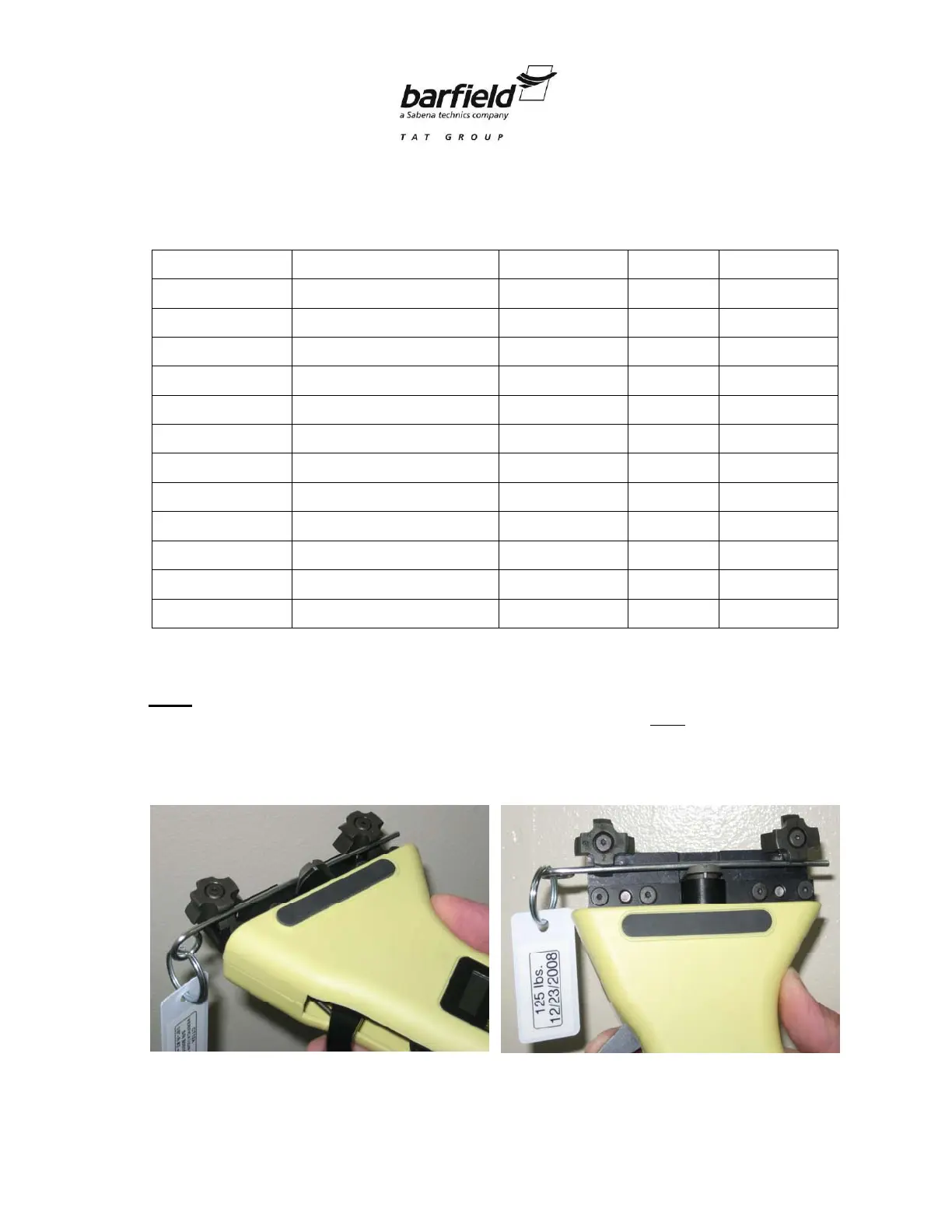
Place the Verification Bar on risers as shown in Fig. 7.
Figure 7: Two views of the correct placement of the Verification Bar in the CT12A