16
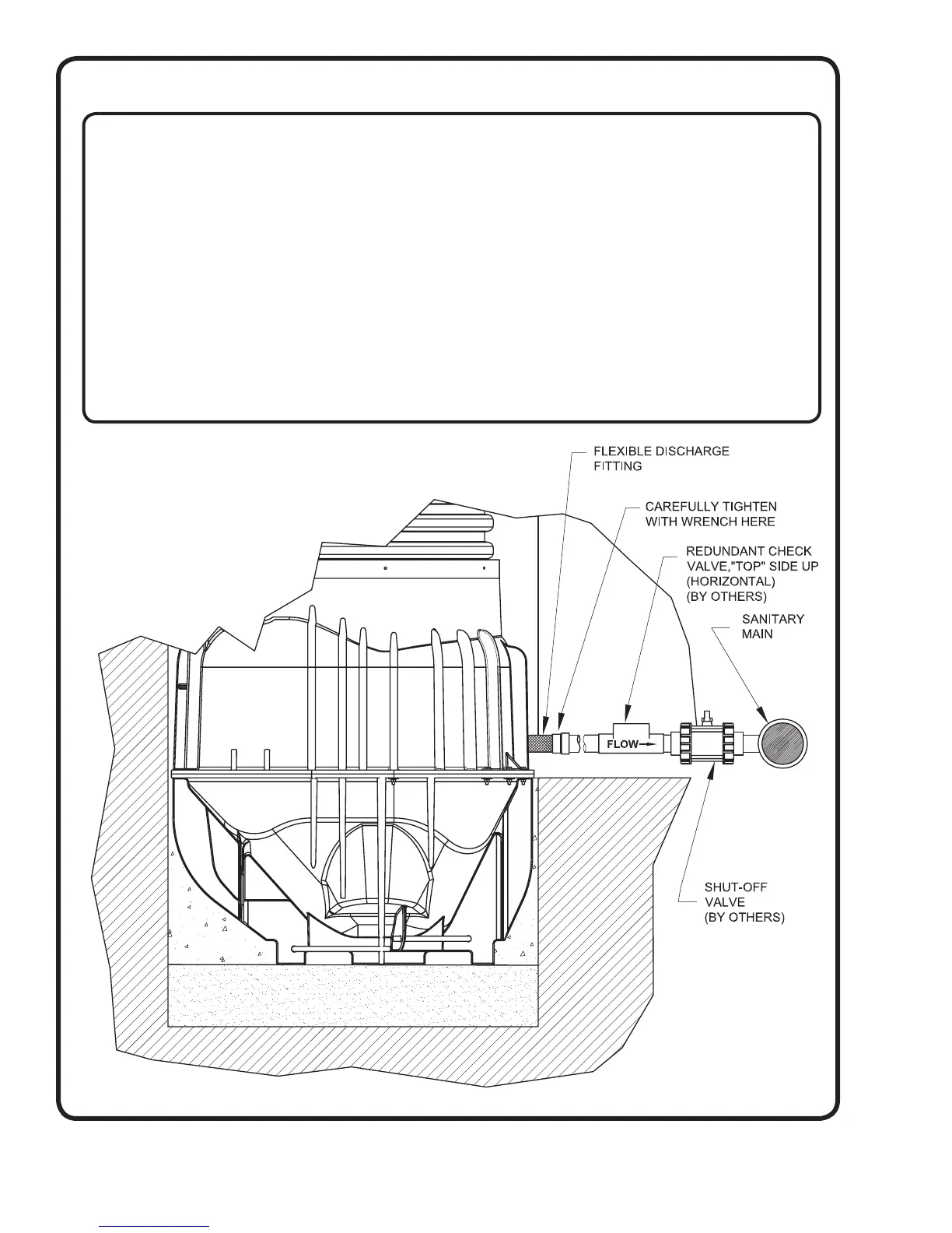
STEP 9: DISCHARGE CONNECTIONS
The basin is equipped with a female 1.25 inch NPT discharge connection.
Your discharge MUST include the following items:
• (1) Flexible pipe coupling –supplied with station to compensate for varied settling rates of backfi ll materials
• (1) Flap style redundant check valve – supplied by others - to prevent backfl ow from the main into the lateral.
CHECK ORIENTATION TO ENSURE PROPER FLOW.
• (1) Shut-off valve – supplied by others - near force main connection for station isolation from main. This valve
is to be placed between the force main and redundant check valve
• Pipe of proper size and strength for rated conditions – supplied by others
Important Notes about the discharge:
• All discharge components should be below frost depth. If above frost depth, all components must be properly
insulated to prevent freezing.
• Pressure checking of discharge should not exceed 150 PSI! Prior to checking laterals be sure to close the
shut-off valve inside the station to avoid damage to basin components. All components of your discharge
should have a pressure rating of 150 PSI at 73° F (23°C) or greater.