17
The majority of basin problems originate from excessive infl ow or infi ltration. While all aspects of basin
installation are critical, the inlet installation should not be deviated from! Make sure to fully read this page
before beginning your inlet installation.
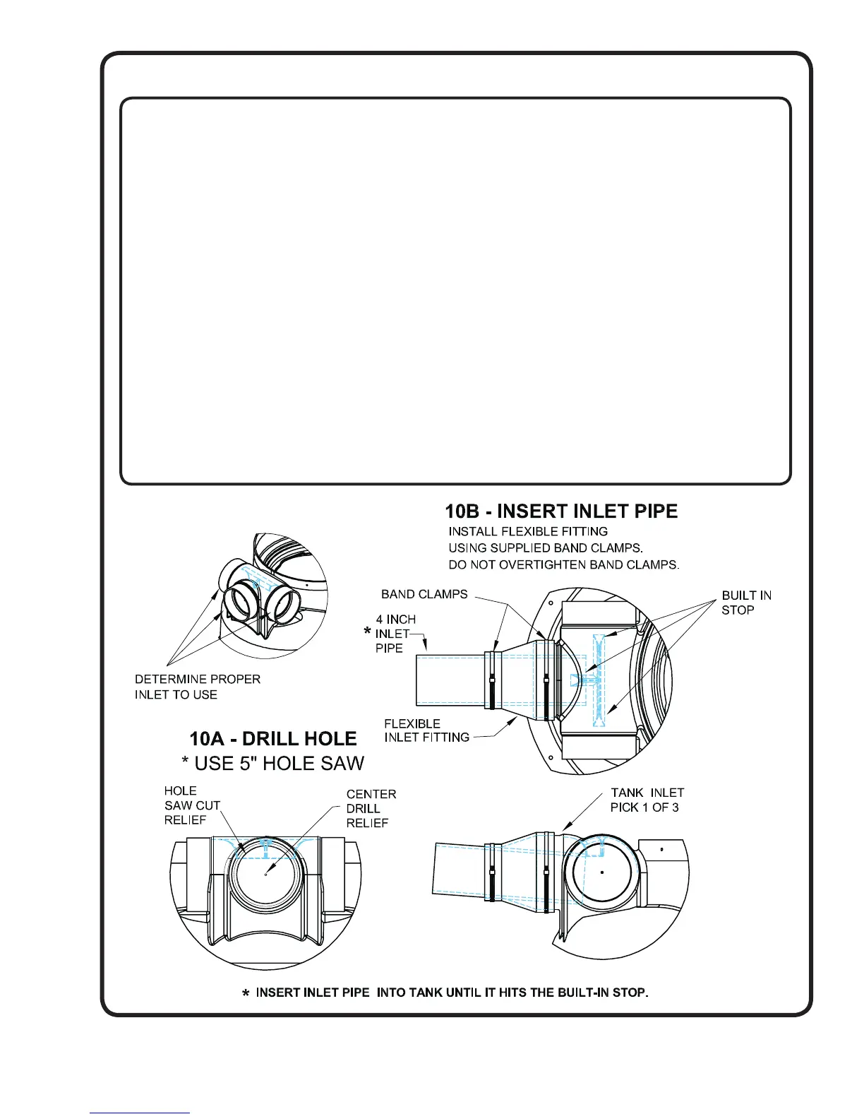
Refer to the illustration below for proper inlet installation. The fl exible inlet fi tting is supplied in the parts box
(see pages 5 & 7). Your basin inlet location should meet the following criteria:
WHAT TO AVOID
• NEVER install additional inlets or additional sources of infl ow unless approved by project engineers. Excessive
amounts of unplanned infl ow will change expected system designs, add possible sources of infi ltration, and
potentially overwork the treatment facilities.
WHAT TO DO
• Verify pipe O.D. The inlet fi tting is sized for 4 inch Schedule 40, 80 and SDR 35
• MUST have a minimum of 1/8” per foot drop. If required only use 45 degree elbows.
INSTALLATION NOTES
• The hole MUST be cut with a 5 inch HOLE SAW to ensure proper sealing around inlet fl ange.
(See Fig. 10A). Use of any other tool or method is prohibited!
• The end of the pipe can be chamfered and lubricated with soapy water to aid in installation.
• Make sure the inlet pipe, tank inlet and inlet fi tting are clean to provided good sealing areas. Install fi tting so the
large diameter of the inlet fi tting is over the tank inlet. Slide inlet pipe thru the inlet fi tting into the tank until it
hits the built in stop.
• Tighten the inlet fi tting band clamps securely.
• Note: 6” pipefi ttings are not to be used with basins.
STEP 10: INLET LOCATION: Installing Flexible Inlet Fittings