Scope:
EXcite
USER MANUAL
BHB 125 / BHB 150
WEB: www.bartec-technor.no PHONE: +47 51 84 41 00 E-MAIL: mail@bartec-technor.no
COMBINED UNIT (24V DC)
LED type:
As same as above LED type in Single Unit (See fig. 4)
Xenon Type: (see Fig. 7)
0: Power input DC 0/COM
+24V: Power input DC 24V +
S1: Switch 1 for alarm stage selection
S2: Switch 2 for alarm stage selection
Fig. 7
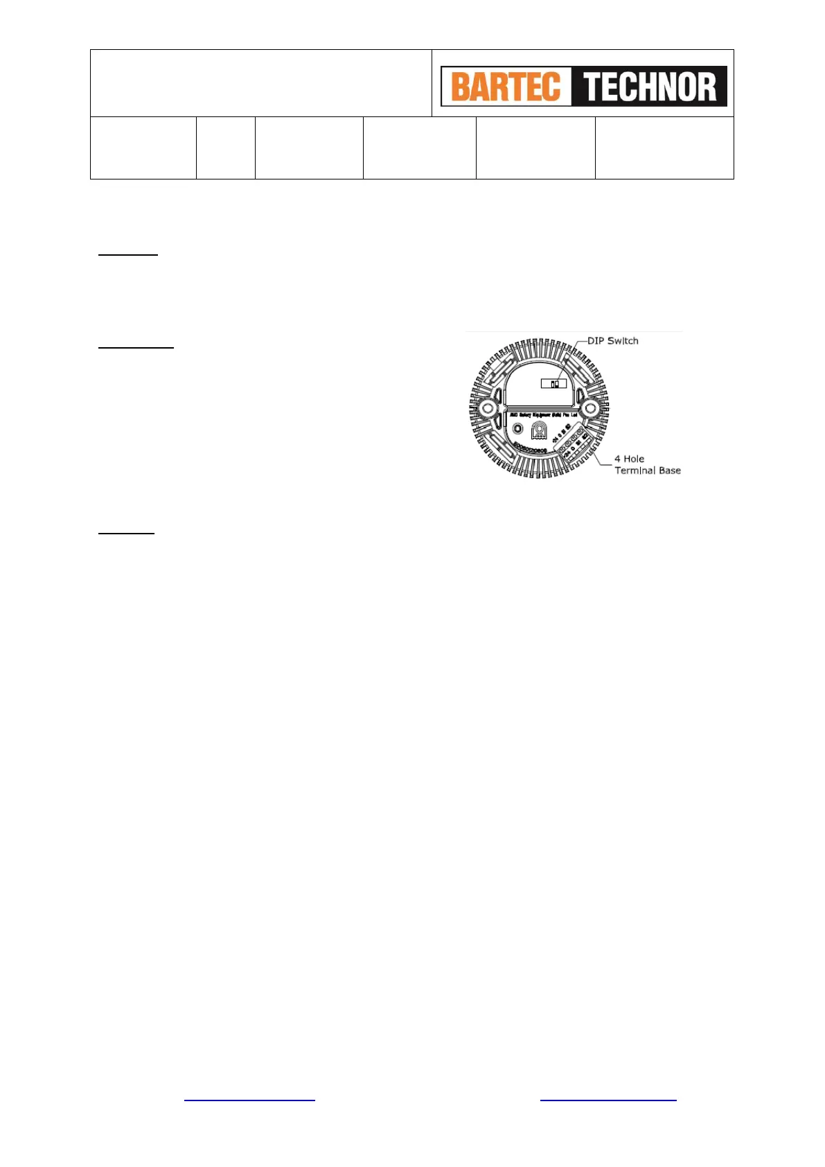
Sounder: (see Fig. 6)
As same as above LED type in Single Unit (See fig. 6)
Four Alarm
S
t
ages
DC Type:
Stage 1: apply power supply to 0/COM and +24V;
Stage 2: apply power supply to 0/COM, +24V and connect S1 to 0/COM;
Stage 3: apply power supply to 0/COM, +24V and connect S2 to 0/COM;
Stage 4: apply power supply to 0/COM, +24V and connect S1, S2 to 0/COM.
7.0 TONE SELECTION
The sounder of BHB provides 64 tones to be selected for the 1st stage alarm. Four stages of alarm tones can
be preset via switch on the Sounder PCB.
Tone Selection Switch
Use the four (4) DIP switches with 6 binary codes on the Sounder PCB to select tones (See Fig 6).
Tone Selection Table (see attached table 1)
 Loading...