Step 8: Determine the required allowance for pumps, valves, flanges and pipe supports:
Determine the required allowances for pumps, valves, flanges and pipe supports using the following table:
→ Example
Pipe diameter: DN25
1 pump
2 valves
6 flanges
24 pipe supports
The total required allowance is calculated as follows:
total required allowance = no. of pumps × pump allowance value +
no. of valves × valve allowance value +
no. of flanges × flange allowance value +
no. of pipe supports × pipe support allowance value
= 1 × 2.1 m + 2 × 0.6 m + 6 × 0.3 m + 24 × 0.3 m
= 12.3 m
Step 9: Add all lengths / allowances together:
Add the lengths for piping (as determined in step 6) and allowances (as determined in step 7 and step 8) together to obtain total required trace
heater length.
→ Example
required trace heater length for piping (step 6): 50 m
required allowances for connection kits (step 7): 1.0 m
required allowances for pumps, valves, flanges and pipe supports (step 8): 12.3 m
total required trace heater length = required trace heater length for piping + required allowances
= 50 m + 1.0 m + 12.3 m
= 63.3 m
Determination of the required number of heating circuits
Step 10: Confirm the number of electrical circuits required for the application:
Using Table G on page 18, compare the required heater length and start up temperature to the available circuit breaker allowances to determine
the number of electrical circuits that will be required.
→ Example
total required trace heater length: 63.3 m
circuit breaker voltage: 230 Vac
selected trace heater: 10 PSB
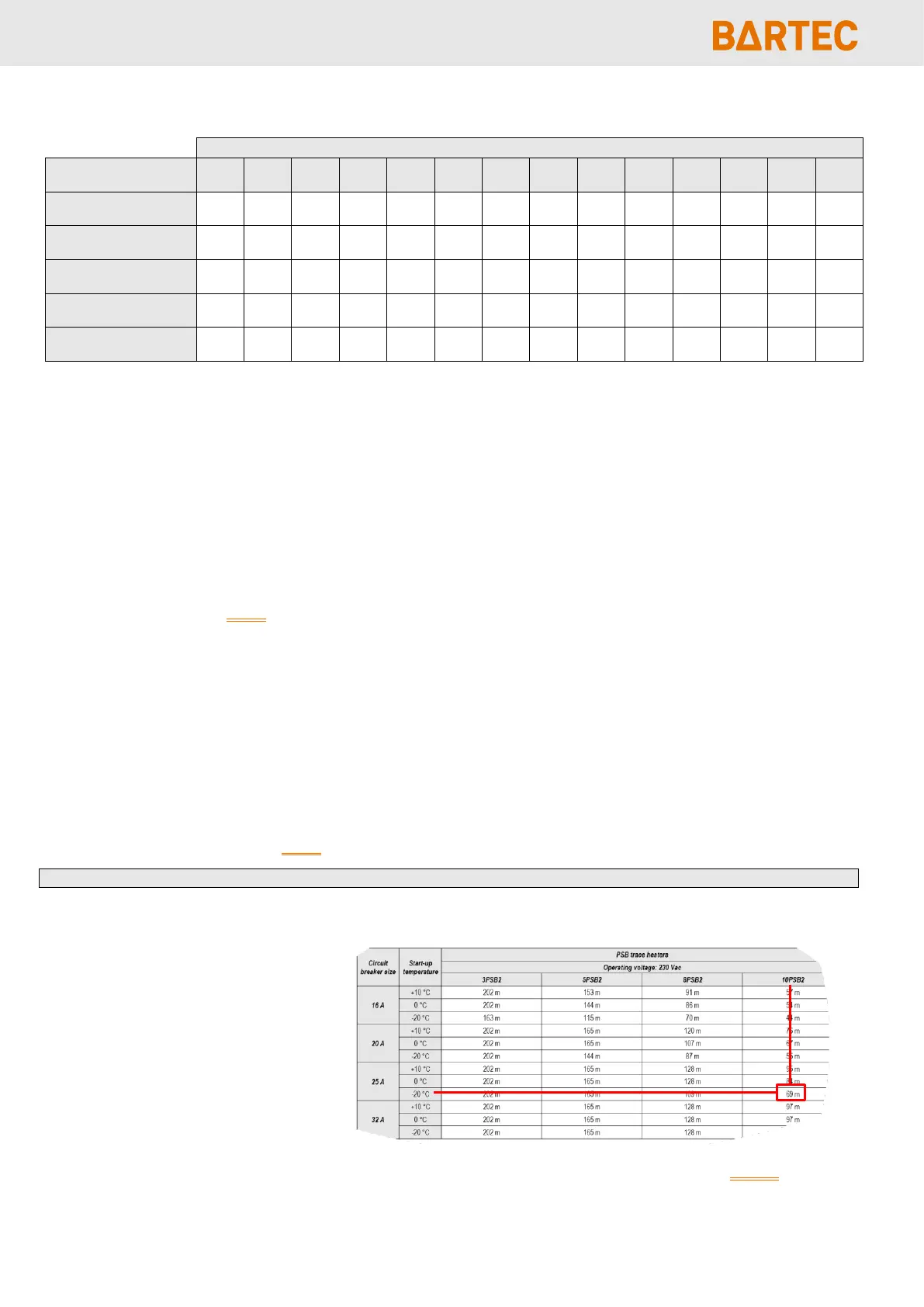
circuit breaker amperage: 25 A
required start-up temperature: -20 °C
allowable trace heater length from table below = maximum of 69 m at -20 °C on 25 A circuit breaker at 230 Vac
= 63.3 m calculated < 69 m maximum allowable for 25 A = 1 circuit