4-4 BE1-50/51B-218/-228 Installation 9252000995 Rev G
4.03
4.03
.31
.75
6.19
(19.1)
(7.9)
(102.4)
(102.4)
(157.2)
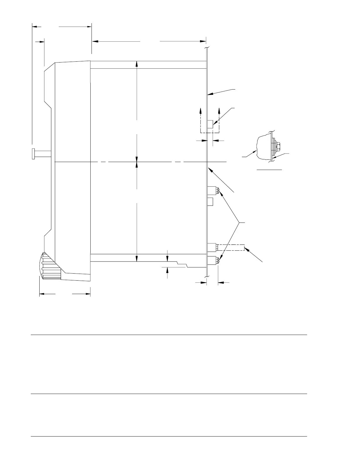
10-32 SCREWS
MOUNTING PANEL
.25
(6.4)
AA
5/16-18 STUD
2 PLACES
TERMINAL EXTENSION (TYP.)
FOR DETAILED INSTRUCTIONS.
SEE THE TERMINAL PROJECTION
MOUNTING KIT SUPPLIED.
MOUNTING PANEL
(62.48)
2.195
(55.75)
(49.53)
1.95
2.40
DETAIL A-A
SHOWING THE ADDITION OF WASHERS
OVER THE BOSS TO TIGHTEN THE
RELAY AGAINST THE PANEL.
CASE
PANEL
12-17-99
D2750-25
NOTE: PROJECTION MOUNT USES WASHERS OVER THE BOSSES AS SHOWN IN THIS ILLUSTRATION.
Figure 4-4. Panel Drilling Diagram for S1 Case, Side View, Projection Mounting
FACTORY SETTINGS
Factory settings for the internal switches of SW3 are as follows:
• SW3-1 — OFF (60 hertz operation).
• SW3-2 — OFF (0.0 additional fixed delay for the instantaneous element).
• SW3-3 — ON (GE IAC type characteristic curves).
• SW3-4 — ON (Integrating reset characteristics).
APPLICATION COORDINATION
In a typical application coordination scheme, a BE1-50/51B-218 or BE1-50/51B-228 is being used to
provide primary protection for a radial distribution feeder. An electromechanical overcurrent relay with
extremely inverse timing provides protection for the transformer and bus. To improve coordination with
the electromechanical relay, the BE1 relay with integrating reset characteristic has the time characteristic

 Loading...


