4-6 BE1-50/51B-218/-228 Installation 9252000995 Rev G
Equation for time to trip during rewind (before relay is reset).
)
)
RewindFull
Time RewindTrip Full
T
Occurence This Trip
=
Second Operation
)
)
15.5
30.209
T
B
=
seconds 0.040T
B
Third Operation
)
)
15.5
11.960.209
T
C
=
seconds 0.161T
C
CONNECTIONS
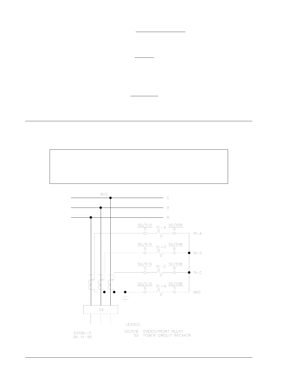
Typical ac input and dc control connections are shown in Figures 4-6 and 4-7. Refer to the block diagram
in Section 3 for relay internal connections.
Figure 4-6. AC Input Connections
NOTE
Be sure that the relay is hard-wired to earth ground with no smaller than 12 AWG
copper wire attached to the ground terminal on the rear of the unit case. When
the relay is configured in a system with other devices, it is recommended to use a
separate lead to the ground bus from each unit.

 Loading...


