9171000990 Rev E BE1-50 Testing 5-1
SECTION 5 • TESTING
INTRODUCTION
The following procedures verify proper relay operation and calibration.
Results obtained from these procedures may no fall within specified tolerances. When evaluating results,
consider three prominent factors:
• Test equipment accuracy
• Testing method
• External test set components tolerance level
OPERATIONAL TEST
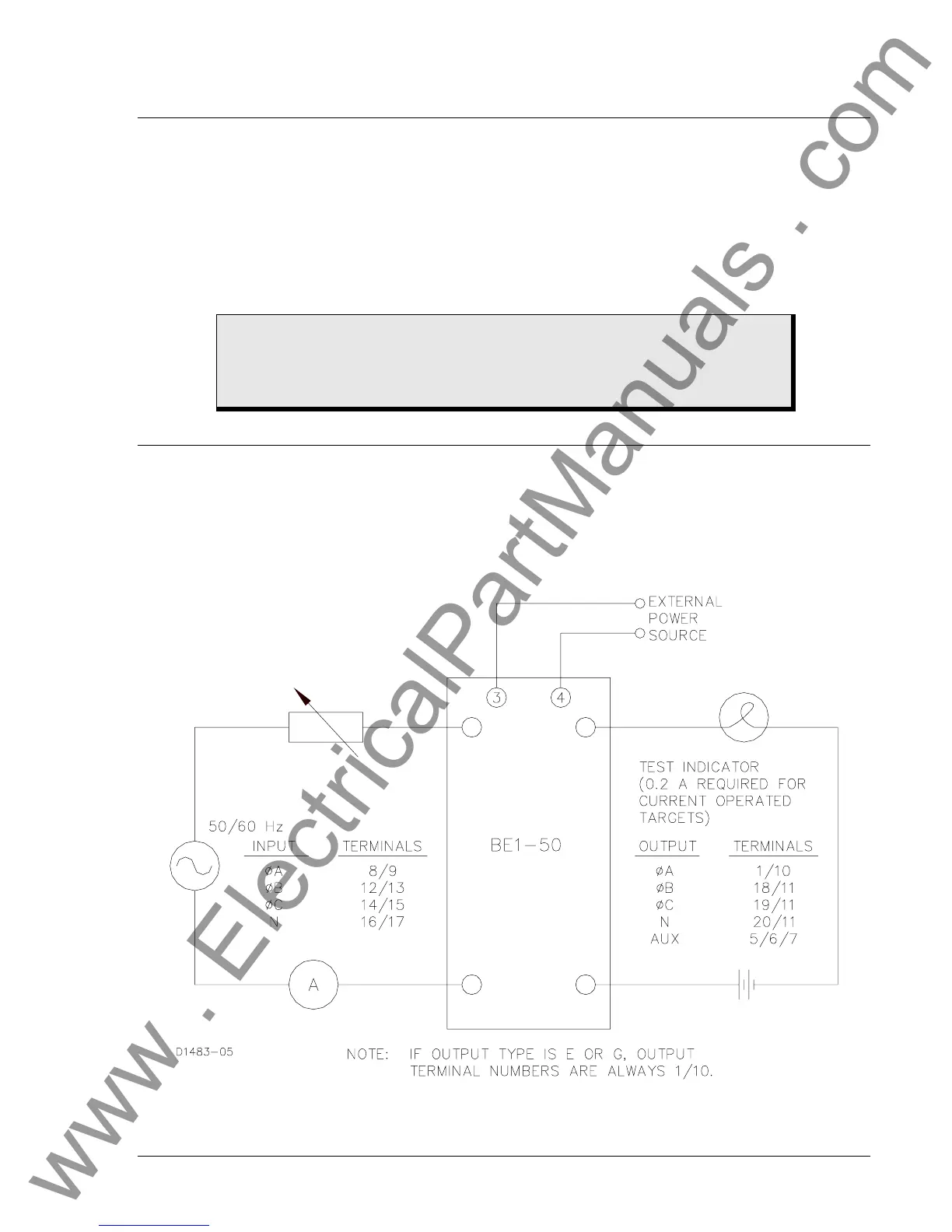
Step 1. Connect the test circuit shown in Figure 5-1. For relay styles with power supply types O, P, R,
S, or T, apply appropriate operating power to terminals 3 and 4. If equipped with power supply
status contacts (option 3-6), verify that these contacts when external power is applied. Remove
input power and verify that the status contacts close. (For relay styles with power supply types
F, G, and H, the relay is powered from the current sensing inputs.)
Figure 5-1. Test Circuit Connection
CAUTION
When adjusting for currents higher than 20 amperes AC, do NOT allow sustained
current flow longer than thirty seconds. Allow a minimum one minute cooling time
between applications.
www . ElectricalPartManuals . com