9171000990 Rev E BE1-50 Controls and Indicators 2-1
SECTION 2 • CONTROLS AND INDICATORS
INTRODUCTION
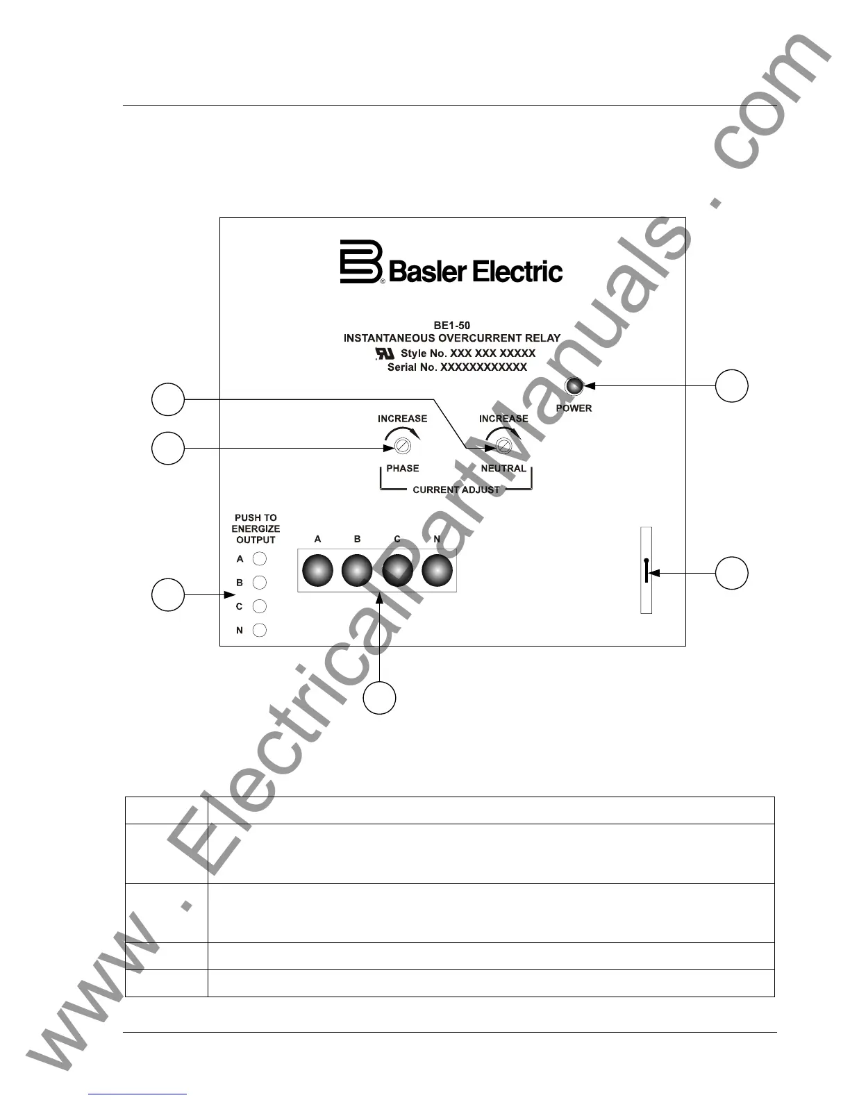
All BE1-50 controls and indicators are located on the front panel. The controls and indicators are shown
in Figure 2-1 and described in Table 2-1. Figure 2-1 illustrates a relay with the maximum number of
controls and indicators. Your relay may not have all of the controls and indicators shown and described
here.
P0050-26
A
B
C
D
E
F
Figure 2-1. BE1-50 Controls and Indicators
Table 2-1. Control and Indicator Descriptions
Locator Description
A
Phase Current Adjust. This multi-turn potentiometer sets the pickup point for all phase
overcurrent elements within the relay. Continuously adjustable over the range defined by
the style number.
B
Neutral Current Adjust. This multi-turn potentiometer sets the pickup point for the neutral
overcurrent element within the relay. Continuously adjustable over the range defined by
the style number.
C Power Indicator. This red LED lights when operating power is applied to the relay.
D Target Reset Switch. This switch is operated to reset the target indicators.
www . ElectricalPartManuals . com