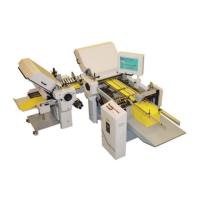
13.3 Remove the cover from the fold plate electrical box.
13.4 Unplug the (2) connectors 7-2 going from the motor to the drive board.
13.5 Remove the (4) screws 7-1 that connect the fold plate electrical box to the casting.
1 2 3
Fig. 7
13.6 Slide the fold plate electrical box 7-3 off of the motor.
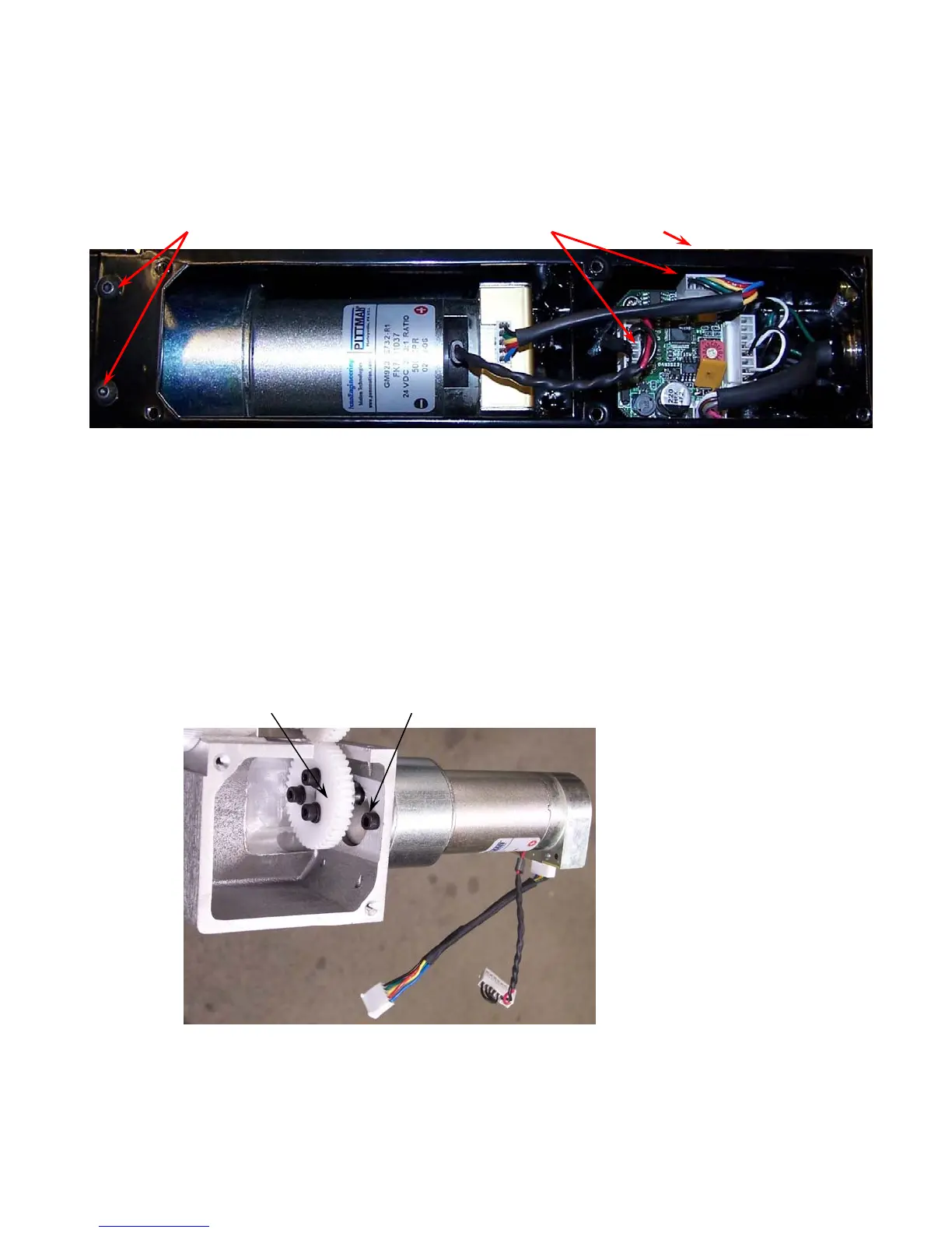
13.7 Remove the (4) set screws from the motor gear hub so it can be removed from the motor shaft.
Note: (2) set screws per hole.
13.8 Remove gear 8-1 from motor shaft.
13.9 Remove the (2) mounting screws 8-2 holding the motor and remove the motor.
13.10 Install the new motor, motor orientation must be the same as the removed motor see figure 8.
1 2
Fig. 8
13.11 Insert gear 8-1 onto motor shaft, align gears and set screw must sit on flat of motor shaft. Note: set
screws must be reinstalled with blue LOCTITE, (2) set screws per hole in gear hub.
13.12 Mount motor guard, reconnect motor wire connectors and reinstall covers.