39
7217395.01 - en
INSTRUCTIONS PERTAINING TO THE INSTALLER
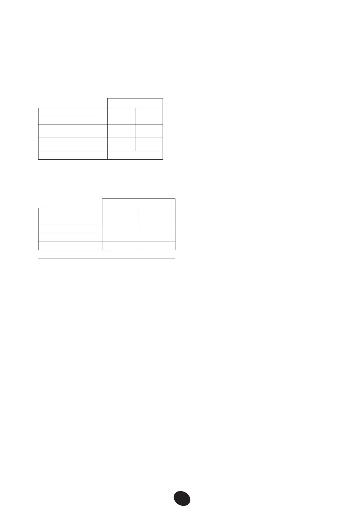
Table of burner pressures
240 i
Gas used G20 G31
nozzle diameter (mm) 1,18 0,74
Burner pressure (mbar*)
REDUCED HEAT OUTPUT
1,9 4,7
Burner pressure (mbar*)
NOMINAL HEAT OUTPUT
10,0 26,0
no. of nozzles 15
* 1 mbar = 10,197 mm H
2
O
Table 1
240 i
Gas consumption
at 15 °C - 1013 mbar
G20 G31
Nominal heat output 2,78 m
3
/h 2,04 kg/h
Reduced heat output 1,12 m
3
/h 0,82 kg/h
p.c.i. 34,02 MJ/m
3
46,3 MJ/kg
Table 2
C2) Adjustment to reduced heat output
• disconnect the modulator feeding cable and unscrew the (b) Fig. 8 screw to reach the pressure setting corresponding
to reduced heat output (see table 1);
• connect the cable again;
• t the modulator cover and seal.
C3) Final checks
• apply the additional dataplate, specifying the type of gas and settings applied.