38
13.0 Servicing
© Baxi Heating UK Ltd 2013
13.2 Annual Servicing - Inspection (Cont)
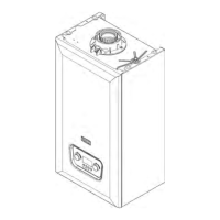
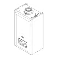
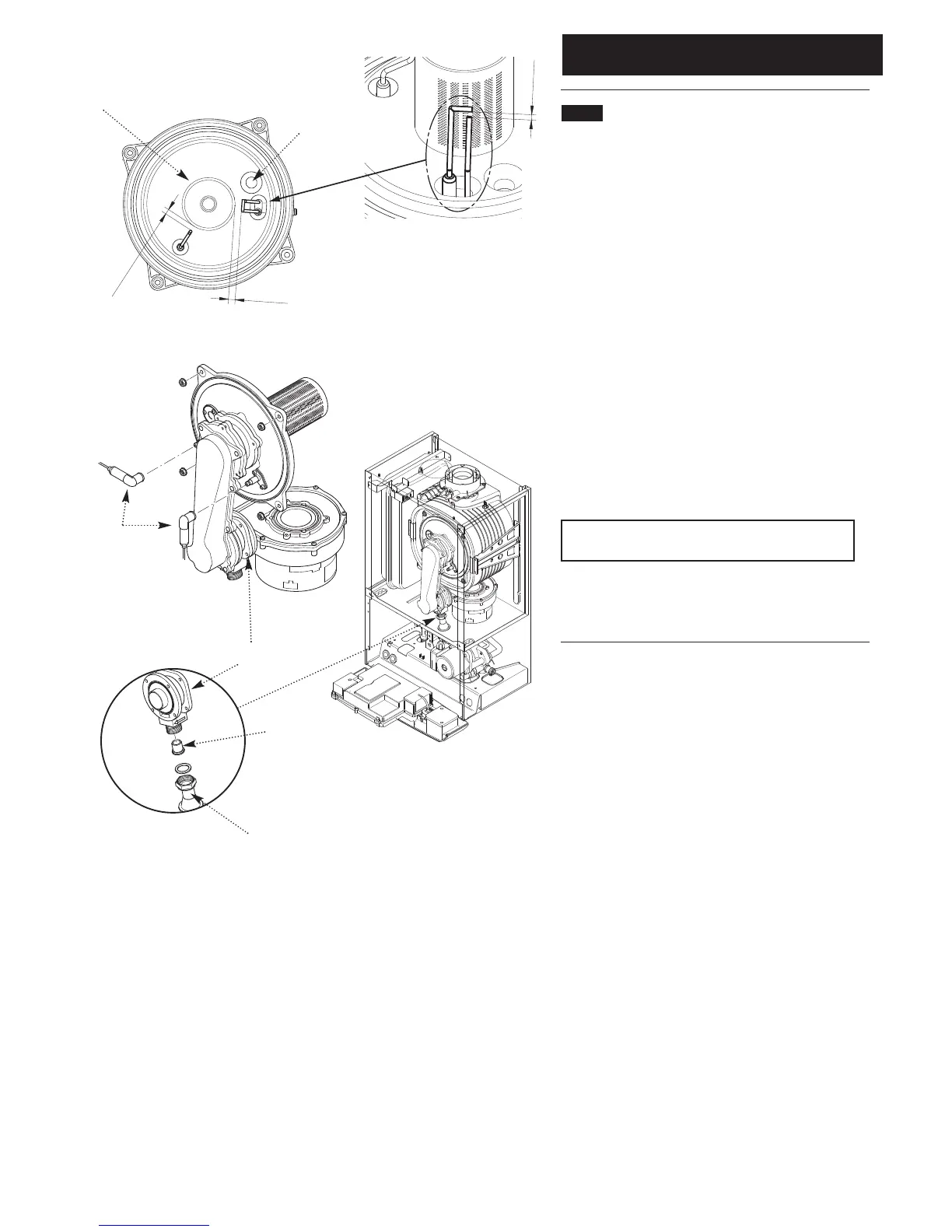
6. Undo the nut on the gas inlet pipe to the venturi (Fig. 63)
and pull the sensing pipe off the fan.
7. Disconnect the electrode leads, noting their position, and
the fan electrical plugs (Fig. 62).
8. Undo the four nuts retaining the combustion box cover
to the heat exchanger.
9. Carefully draw the fan, collector and cover assembly
forward, being careful to retain the injector in the venturi
(Figs. 62 & 63).
10. Clean any debris from the heat exchanger and check
that the gaps between the tubes are clear.
11. Inspect the burner, electrodes position and insulation,
cleaning or replacing if necessary. Clean any dirt or dust
from the air box.
12. Reassemble in reverse order.
NOTE: The sensing pipe must be reconnected to the
fan, not the venturi.
13. Complete the relevant Service Interval Record section of
the Benchmark Commissioning Checklist at the rear of this
publication and then hand it back to the user.
Fig. 62
Fig. 63
Gas Inlet Pipe
Venturi
Injector
Fan, Collector and Cover
Assembly
Electrode
Leads
7.5
±
1
4
±
0.5
1
0
±
1
Spark Ignition
Electrode
Sensing
Electrode
Electrode Position
Viewing Window
Burner
 Loading...