8
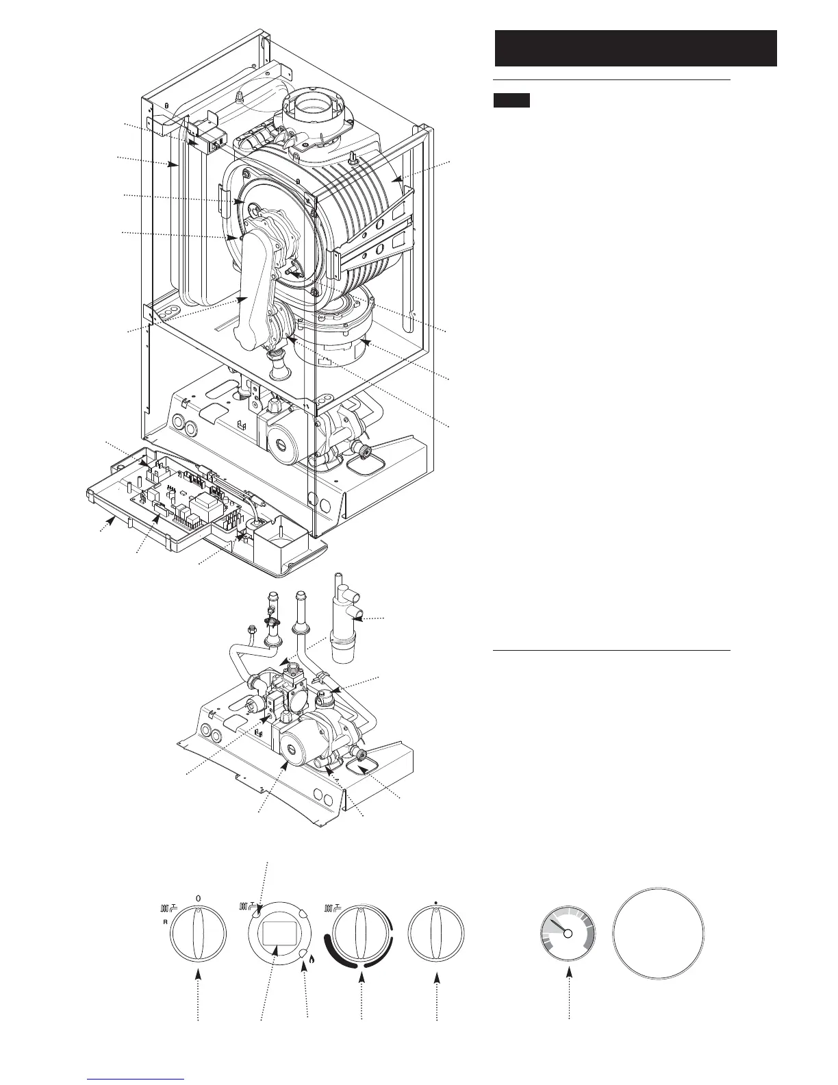
2.0 General Layout
© Baxi Heating UK Ltd 2013
2.1 Layout
1. Expansion Vessel
2. Automatic Air Vent
3. Circulation Pump
4. Drain Off Point
5. Pressure Relief Valve
6. Selector Switch
7. Central Heating System Pressure Gauge
8. PCB
9. Control Box
10. Gas Valve
11. Condensate Trap
12. Flame Sensing Electrode
13. Spark Electrode
14. Primary Heat Exchanger
15. Fan Assembly
16. On/Off/Reset Selector Switch
17. Central Heating Temperature Control
18. Calibration Control
19. Venturi
20. Air/Gas Collector
21. Combustion Box Cover & Burner
22. Igniter
23. Burner On Light
24. Central Heating Mode Light
25. Display
1
16
17
18
7
bar
0
1
2
3
4
21
2
3
4
5
6
7
8
9
10
11
12
13
14
15
19
20
22
23
24
25
 Loading...