page 5
© Baxi Heating UK Ltd 2011
Y
X
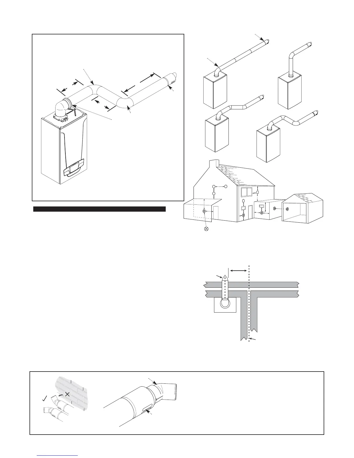
NOTE: Horizontal flue pipes should always be installed with a 1.5° to 3°
fall from the terminal to allow condensate to run back to the boiler.
Push the flue deflector over the terminal end and rotate to the
optimum angle for deflecting plume. Secure the deflector to the
terminal with screw provided.
Do not direct the deflector upwards or downwards.
NOTE: A terminal guard is still required when circumstances
dictate (B.S. 5440-1).
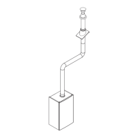
FLUE OPTIONS
Horizontal Flue System Examples
Z
Y
This bend is equivalent to
1 metre
For Ø60/100 Flue Systems
Total equivalent length =
A+B+C+2x90°Bends
B
A
C
This bend is equivalent to
1 metre
DO NOT DIRECT THE FLUE DEFLECTOR TOWARDS A WALL.
Flue Terminal
Flue Deflector
The MAXIMUM total equivalent length
is stated in the Installation & Servicing
Instructions supplied with each boiler.
Terminal Position with Minimum Distance (mm)
A
1
Directly below an opening, air brick, opening
windows, etc. 300
B
1
Above an opening, air brick, opening window etc. 300
C
1
Horizontally to an opening, air brick, opening window etc. 300
D
2
Below gutters, soil pipes or drain pipes. 25
E
2
Below eaves. 25
F
2
Below balconies or car port roof. 25
G
2
From a vertical drain pipe or soil pipe. 25
H
2
From an internal or external corner. 25
I Above ground, roof or balcony level. 300
J From a surface or boundary line facing a terminal. 600
K From a terminal facing a terminal (Horizontal flue). 1200
From a terminal facing a terminal (Vertical flue). 600
L From an opening in carport (e.g. door, window)
into the dwelling. 1200
1
In addition, the terminal should be no nearer than 150 mm to an
opening in the building fabric formed for the purpose of accommodating a
built-in element such as a window frame.
2
Only ONE 25mm clearance is allowed per installation. If one of the
dimensions D, E, F, G or H is 25mm then the remainder MUST be as
B.S.5440-1.
NOTE: The distance from a fanned draught appliance terminal
installed parallel to a boundary may not be less than 300mm in
accordance with the diagram below
*
* Reduction to the boundary is possible down to 25mm but flue deflector
part no. 5111068 must be used.