23
9.0 Installation
© Baxi Heating UK Ltd 2007
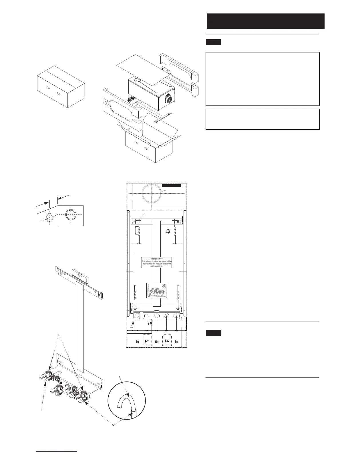
9.1 Unpacking & Initial Preparation
IMPORTANT
RISK ASSESSMENT - Before commencing the installation
it is recommended that the ‘Five Steps to Risk
Assessment’ document published by the HSE is consulted,
and an assessment performed as described.
GAS SUPPLY - The gas supply, gas type and pressure
must be checked for suitability before connection (see
Section 7.4).
NOTE: a small amount of water may drain from the boiler
in the upright position. If pre-plumbing it will be necessary
to turn the carton over to access the wall plate first.
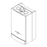
1. Remove staples, open flaps and remove the cardboard
sheet. Remove the polystyrene side pieces and literature. Two
people can then lift out the boiler (Fig. 17).
2. After considering the site requirements
(see Section 7.0) position the fixing template on the wall
ensuring it is level both horizontally and vertically.
3. Mark the position of the two most suitable fixing slots for
the wall plate and boiler lower fixing holes.
4. Mark the position of the centre of the flue hole (rear exit).
For side flue exit, mark as shown (Fig. 18).
5. If required, mark the position of the gas and water pipes.
Remove the template.
6. Cut the hole for the flue (minimum diameter 116mm).
7. Drill the wall as previously marked to accept the wall plugs
supplied. Secure the wall plate using the fixing screws.
8. Using a spirit level ensure that the plate is level before finally
tightening the screws.
9. Connect the gas and water pipes to the valves on the wall
plate using the copper tails supplied. Ensure that the sealing
washers are fitted between the connections.
10. Fit the filling loop as described in the instructions supplied
with it.
9.2 Flushing
1. Connect a tube to the heating flow or return pipe (Fig. 20).
2. Make the flow and return connections to the isolation taps.
Flush the system thoroughly to remove all impurities (see
System Details, Section 6.2).
Fig. 20
130mm
For Side Flue Exit
Heating Return
Flushing Tube
Fig. 18
Fig. 19
Fig. 17
Pressure
Relief
Valve
(15mm)
Condensate
Drain
Part No. 720636502
5 mm Minimum
Side Clearance
5 mm Minimum
Side Clearance
116mm Dia Minimum
Aperture For Flue Tube
Side Flue
Centre Line
Vertical Flue
Centre Line
175 mm
Minimum
Clearance
Profile of
Outercase
228 mm
150 mm
Minimum
Clearance
Boiler Mounting Bracket
Fixing Slots
40 mm
25
mm
65 mm 65 mm 65 mm 65 mm 65 mm
Ø 8 mm
Ø 8 mm
50 mm
162.5 mm
Hot Water
Outlet
(15mm)
Combi Only
Not System
Cold Water
Inlet
(15mm)
Heating
Return
(22mm)
Heating
Flow
(22mm)
Gas
Inlet
(22mm)
Combi Only
Not System
Part No. 720636502
View from Underneath
200 mm
Recommended
Heating Flow
3/4” BSP
Connections
 Loading...