9
3.0 Appliance Operation
© Baxi Heating UK Ltd 2012
3.1 Central Heating Mode
1. With a demand for heating, the pump circulates water
through the primary circuit.
2. Once the burner ignites the fan speed controls the gas
rate to maintain the heating temperature measured by the
temperature sensor.
3. When the flow temperature exceeds the setting
temperature, a 3 minute delay occurs before the burner
relights automatically (anti-cycling). The pump continues to
run during this period.
4. When the demand is satisfied the burner is extinguished
and the pump continues to run for a period of 3 minutes
(Pump Overrun).
3.2 Domestic Hot Water Mode
1. Priority is given to the domestic hot water supply. A
demand at a tap or shower will override any central heating
requirement.
2. The flow of water will operate the Domestic Hot Water
Sensor (‘Hall Effect Sensor’) which requests the 3 way valve
to change position. This will allow the pump to circulate the
primary water through the DHW plate heat exchanger.
3. The burner will light automatically and the temperature of
the domestic hot water is controlled by the temperature
sensor.
4. When the domestic hot water demand ceases the burner
will extinguish and the diverter valve will remain in the
domestic hot water mode, unless there is a demand for
central heating.
3.3 Boiler Frost Protection Mode
1. The frost protection mode is integral to the appliance and
functions as long as there is power to the boiler, as indicated
by the standby signal .
2. With CH & DHW or CH only selected, when the boiler
temperature falls below 5°C the boiler will fire until a
temperature of 30°C is reached.
3. If DHW only is selected, when the boiler CH temperature
falls below 5°C the boiler will fire until a temperature of
30°C is reached. When the boiler DHW temperature falls
below 5°C the boiler will fire until a temperature of 7°C is
reached.
4. Further protection can be incorporated by using a system
frost thermostat.
3.4 Pump Protection
1. If the boiler has been inactive for a period of 24 hours the
pump will automatically operate for 1 minute to prevent
sticking.
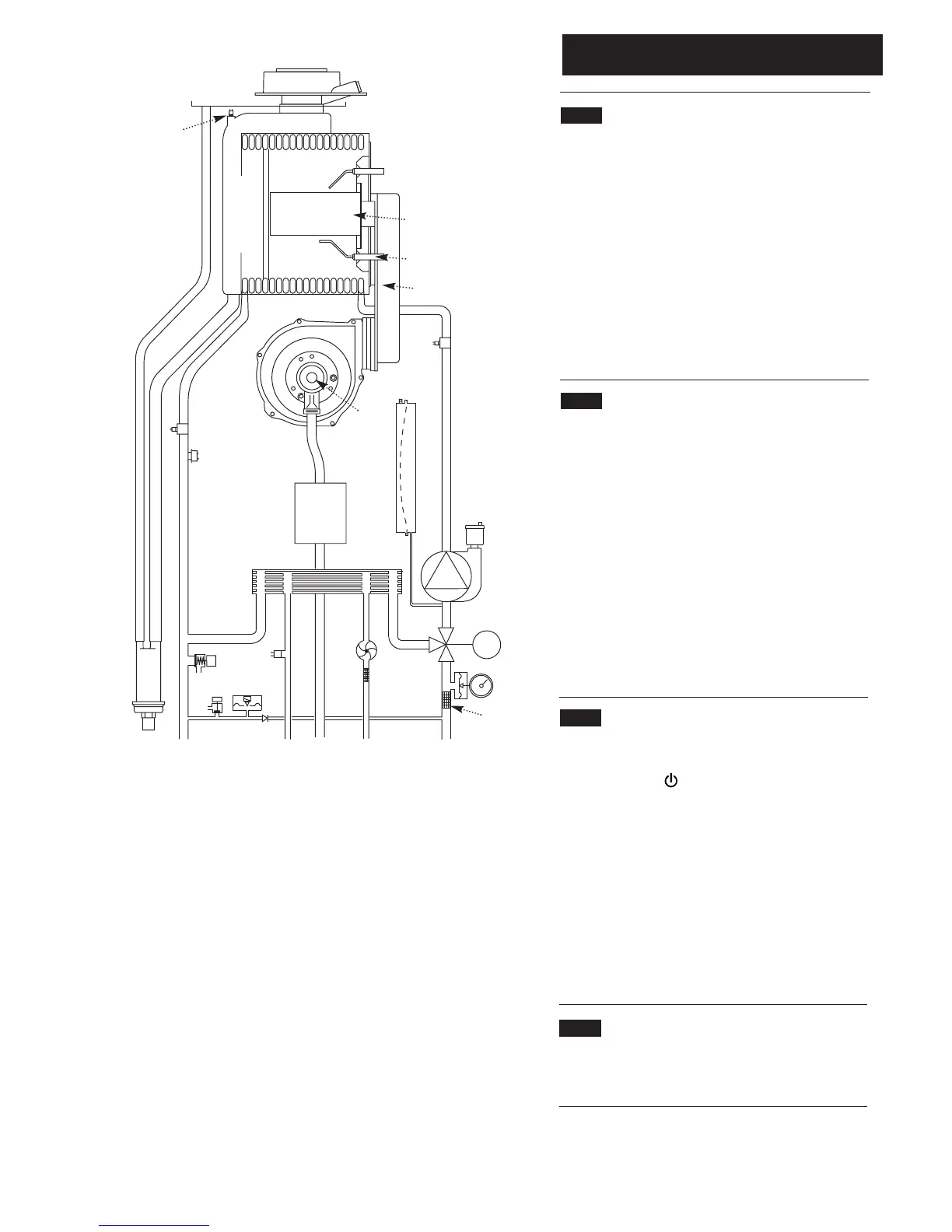
M
Key
1. Pump with Automatic Air Vent
2. Diverter Valve Assembly
3. Diverter Valve motor
4. CH System Pressure Gauge
5. Central Heating Filter
6. Domestic Hot Water Filter
7. Domestic Hot Water Priority Sensor
(‘Hall Effect Sensor’)
8. Domestic Hot Water NTC sensor
9. Non-return Valve
10. Hydraulic Pressure Sensor
11. Boiler Drain Tap
12. Pressure Relief Valve
13. Plate Heat Exchanger
14. Condensate Trap
15. Gas Valve
16. Safety Thermostat (105°C)
17. Heating Flow Sensor
18. Flue Sensor
19. Boiler Adaptor
20. Primary Heat Exchanger
21. Spark Ignition Electrode
22. Burner
23. Flame Sensing Electrode
24. Air/Gas Collector
25. Return Heating Sensor
26. Fan
27. Air/Gas Venturi
28. Expansion Vessel
Connections:-
A – Condensate Drain
B – Heating Flow
C – Domestic Hot Water Outlet
D – Gas Inlet
E – Cold Water Inlet On/Off Valve and filter
F – Heating Return
Fig. 3
1
2
3
4
5
6
7
8
9
10
11
12
13
15
16
14
17
18
19
20
21
22
23
24
25
26
28
27
A
B
C
D
E
F
Boiler Schematic
Layout
 Loading...