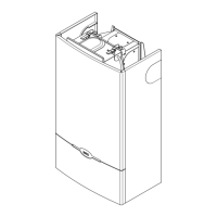
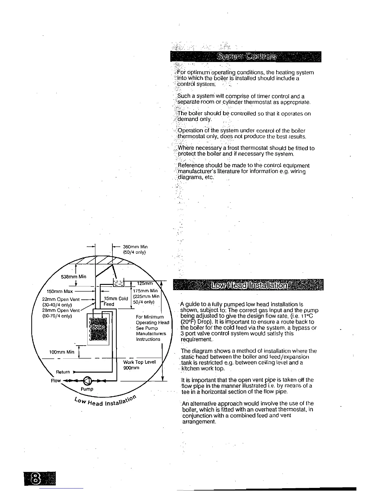
360mm Min
(50/4 only)
125mm
xk
r
kt
ri').
;;;;
O
Viltgl
ks
For optimum operating conditions, the heating system
'into which the boiler is installed should include a
-
control system.
Such a system will comprise of timer control and a
'
,
separate room or cylinder thermostat as appropriate.
The boiler should be controlled so that it operates on
demand only.
Operation of the system under control of the boiler
thermostat only, does not produce the best results.
Where necessary a frost thermostat should be fitted to
protect the boiler and if necessary the system.
Reference should be made to the control equipment
manufacturer's literature for information e.g. wiring
•
diagrams, etc.
175mrn Min
(225mm Min
50/4 only)
For Minimum
Operating Head
See Pump
Manufacturers
Instructions
538mm Min
150mm Max
22mm Open Vent
(30-40/4 only)
28mm Open Vent
(50-70/4 only)
100mm Min
I
Return
Row '1 I
CD
C
to
0(t
Iv
Head Insta
%
lla
•
A guide to a fully pumped low head installation is
shown, subject to: The correct gas input and the pump
being adjusted to give the design flow rate, (i.e. 11°C
(20°F) Drop). It is important to ensure a route back to
the boiler for the cold feed via the system, a bypass or
3 port valve control system would satisfy this
requirement.
The diagram shows a method of installation where the
static head between the boiler and feed/expansion
tank is restricted e.g. between ceiling level and a
•
kitchen work top.
It is important that the open vent pipe is taken off the
flow pipe in the manner illustrated i.e. by means of a
tee in a horizontal section of the flow pipe.
An alternative approach would involve the use of the
boiler, which is fitted with an overheat thermostat, in
conjunction with a combined feed and vent
arrangement.
 Loading...