Installation
CONNECTION OF HIGH PRESSURE HOSE
NOTICE
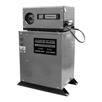
THE MACHINE MUST BE PLACED IN A HORIZONTAL POSITION, ON A LEVEL
SURFACE.
Installation and Operating Instructions
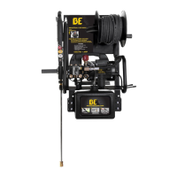
1. Inlet
2. Outlet
3. Pressure Adjustment Knob
4. On/Off Switch
5. Chemical Injector
6. Chemical Filter
8. Oil Dipstick
7. Auto-start System
9. Oil Level Indicator
10. Metal Gun
11. Variable Nozzle
12. High Pressure Hose
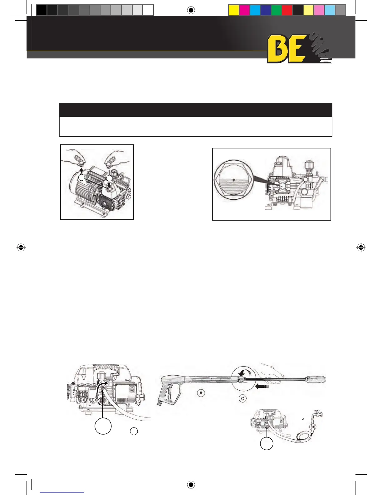
THE MACHINE MUST BE PLACED IN A HORIZONTAL POSITION, ON A LEVEL SURFACE.
Replace the red oil travel plug (1)
with the yellow dipstick (2).
Check that the oil in the sight glass is at
the halfway level.
Connection of high pressure hose:
1. Connect one end of the high pressure hose to the gun (A) and the other to the outlet connection (B).
2. Assemble the lance by pushing the two halves together and then fix by turning the connector (C).
Connection to water supply:
1. The maximum temperature of the inlet water must not exceed 140 F.
o
2. Connect the water supply to the INLET port by means of a reinforced hose (200 PSI) with internal diameter of no
less than 13 mm (1/2”).
3. Considering that the water flow decreases in accordance with the length of the hose, make sure that the quantity
of water reaching the machine is at least 2.7 GPM.
13 mm
INLET
1
6
2
5
3
4
8
9
OUTLET
CHEM
11
12
10
7
OUTLET
B
INLET
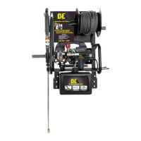
Installation and Operating Instructions
1. Inlet
2. Outlet
3. Pressure Adjustment Knob
4. On/Off Switch
5. Chemical Injector
6. Chemical Filter
8. Oil Dipstick
7. Auto-start System
9. Oil Level Indicator
10. Metal Gun
11. Variable Nozzle
12. High Pressure Hose
THE MACHINE MUST BE PLACED IN A HORIZONTAL POSITION, ON A LEVEL SURFACE.
Replace the red oil travel plug (1)
with the yellow dipstick (2).
Check that the oil in the sight glass is at
the halfway level.
Connection of high pressure hose:
1. Connect one end of the high pressure hose to the gun (A) and the other to the outlet connection (B).
2. Assemble the lance by pushing the two halves together and then fix by turning the connector (C).
Connection to water supply:
1. The maximum temperature of the inlet water must not exceed 140 F.
o
2. Connect the water supply to the INLET port by means of a reinforced hose (200 PSI) with internal diameter of no
less than 13 mm (1/2”).
3. Considering that the water flow decreases in accordance with the length of the hose, make sure that the quantity
of water reaching the machine is at least 2.7 GPM.
2
1
INLET
1
6
2
5
3
4
8
9
OUTLET
CHEM
11
12
10
7
OUTLET
B
INLET
Replace the red oil travel plug (1)
with the yellow dipstick (2).
Check that the oil in the sight glass
is at the halfway level.
1. Connect one end of the high pressure hose to the gun (A) and the other to the
outlet connection (B).
2. Assemble the lance by pushing the two halves together and then fix by turning the
connector (C).
1. The maximum temperature of the inlet water must not exceed 140ºF.
2. Connect the water supply to the INLET port by means of a reinforced hose (200
PSI) with internal diameter of no less than 13 mm (1/2”).
3. Considering that the water flow decreases in accordance with the length of the
hose, make sure that the quantity of water reaching the machine is at least 2.7
GPM.
CONNECTION TO WATER SUPPLY
P1515EPN_P1515EPWN Genpower Manual_2016.indd 13 1/5/2016 10:59:52 AM
 Loading...