Page 2 of 5 75.5892.03 KEYPADS 20171013
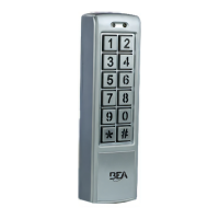
1 Red (power +)
2 Black (power ground)
3 Brown (door magnet)
4 Orange (zone 1 exit button)
5 Yellow (zone 2 exit button)
6 Green (exit button – COM)
7 White (NO)
8 Pink (COM)
9 Aqua (NC)
10 Blue (NO)
11 Purple (COM)
12 Gray (NC)
8”
0.5W recommended
-
+
13 Brown/White (door bell)
14 Black/White (door bell)
Shielding line
}
Input DC: 12V to 24V
Input AC: 12V to 24V
Shield ground
Zone 1
UNLOCK
(dry)
Zone 2
UNLOCK
(dry)
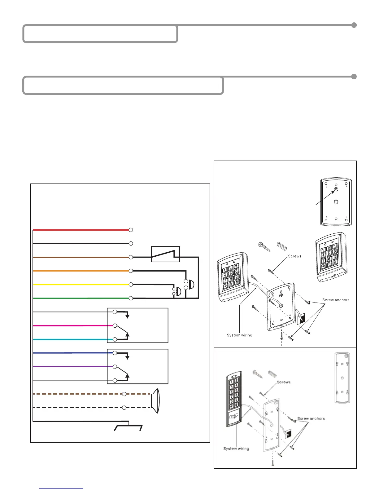
10KEYPADU
10KEYPADU / 10KEYPADUSL
10KEYPADUSL
C
A
A
Page 2 of 5 75.5892.03 KEYPADS 20171013
5 Installation – Mechanical & Electrical
Installation
Wiring
CAUTION: Do not damage
the tamper sensor.
4 Installation Notes
• Handle the equipment with care.
• Add threadlocker to all screws before installing.
• Firmly tighten screws.
1. Using the supplied hex key, remove the backcase screw from the keypad bottom.
2. Use the drilling template and drill required holes. For surface mounting, drill the 4 holes marked as B in the installation image
below; for single gang box mounting, drill the 2 holes marked as A in the installation image below.
3. Mount backcase on the wall with provided screws. Make sure to pull keypad cable through the center hole (marked C, below).
Keep keypad horizontal to the oor.
4. Connect the wires based on the following wiring diagram.
5. Mount keypad to the back cover by using the provided screws.