Do you have a question about the BEA 10KEYPADU and is the answer not in the manual?
Denotes the device's protection against dust and water ingress.
Instructions on using a hex key to remove the backcase screw from the keypad bottom.
Guidance on drilling holes for surface or single-gang box mounting, noting the tamper sensor.
Instructions for attaching the backcase to the wall and routing the cable.
Procedure to enter the device's setup mode using the default administration code.
Steps to change the existing administrator code to a new 4-digit code.
Process to alter the length of the admin code, which resets user codes.
Instructions for adding a user code to the first zone, specifying location and code.
Instructions for adding a user code to the second zone, specifying location and code.
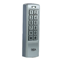
The Universal Keypad Family offers stand-alone access control keypads, available in two models: the 10KEYPADU and the slimmer 10KEYPADUSL. These devices are designed for secure entry management, featuring a matrix keypad for user input, a Door LED to indicate door status, and a Mode LED to show the current operating mode. A case screw, located at the bottom of the case, secures the device.
The keypads offer comprehensive programming options accessible through a "setup" mode, which is entered by inputting the administration code twice. The default administration code is 1234. If forgotten, the administration code can be reset to 1234 by powering off the device, pressing and holding the "#" key, and then powering it back on.
Users simply enter their assigned user code to gain access. If three consecutive invalid keyboard entries occur, the keypad will be disabled for 60 seconds as a security measure.
Specifications are subject to change without prior notice, and all values are measured in specific conditions.