71020 & 70554 Chipper Shredder Owners ManualPage 16
5.5 REPLACING SHREDDER KIT
1. Remove discharge cover and discharge screen.
2. Remove rear side access cover.
3. Work with one knife shaft at a time. Remove #10-24
bolt and nut from knife shaft and discard, do not
reuse.
4. Using a hammer and punch, drive the knife shaft
through the access hole on the rear of the machine.
Service and Maintenance
Never reuse rotor shafts or bolts and nuts if they show
signs of wear or abuse. Install new ones.
NOTE
5
37
7
6
7
5
7
33
7
4
7
7
7
5
6
7
5
9
8
21
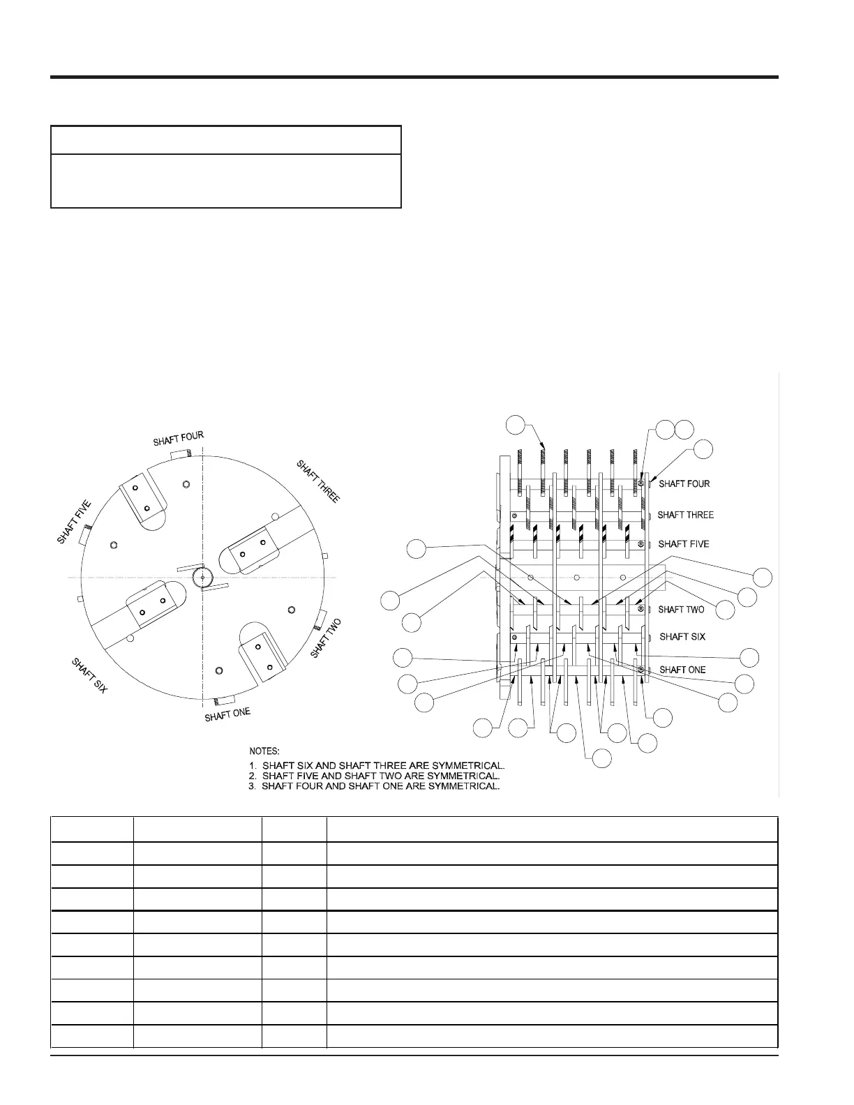
RECTANGULAR SHREDDER KNIVE KIT
TYPICAL SETUP FOR MODEL #'S 70554 & 71020
ITEM # PART # QTY DESCRIPTION
1 15397 6 NUT, # 10 X 24 NYLOCK
2 15466 6 SCREW, 10-24 X 1-1/8
3 70367 10 SHORT SPACER .75 X .59 (LARGE C/S)
4 70368 2 SHORT SPACER-BORED .75 X .59 W/HOLE (LARGE C/S)
5 70369 8 SPACER, .75 X 1.18
6 70370 4 MEDIUM SPACER-BORED .75 X 1.18 W/ HOLE (LARGE C/S)
7 70371 18 LONG SPACER .75 X 1.47 (LARGE C/S)
8 70381 6 ROTOR KNIFE SHAFT (LARGE C/S)
9 70856 36 SHREDDING KNIFE, RECTANGULAR
5. Remove spacers and shredder knives. Be careful to
keep track of the order the spacers were installed on
the shafts so they can be returned to the original
locations. If the spacers and knives are not installed
correctly, the rotor will be out of balance and will not
have proper shredding action.
6. Reverse or replace knives and reassemble back into
the rotor. Install new #10-24 bolt and nut through the
spacer and shaft, then retorque to 36 in lbs.
7. Complete service of all six shafts in this same
process.
8. After the access cover, discharge screen and cover
have been installed, torque all 3/8 bolts to 33 ft lbs.
and test run the machine.
Fig. #15