131
&RQQHFWLRQ,QVWUXFWLRQV
C1
C2
C3
B
A
*36$QWHQ
QDV
$QWHQQD
VRFNHW
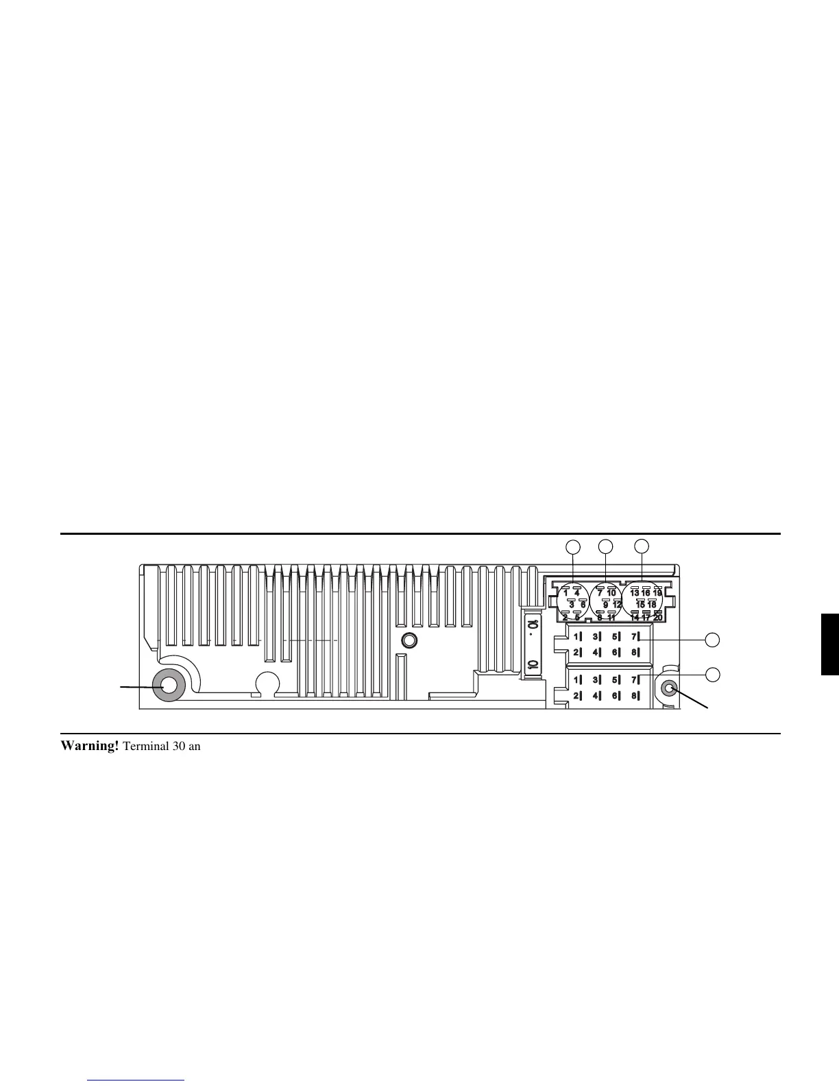
&RQQHFWLRQ,QVWUXFWLRQV
:DUQLQJ Terminal 30 and Terminal 15 must always be connec-
ted separately, otherwise increased power consumption will occur
when the unit is switched off. Connection socket A is not the same
for all vehicle types. Therefore, always measure voltages before in-
stallation.
6RFNHW$
1 Speed Signal (GAL)
2 Reversing lamp signal
3 Telephone mute / clearing function
4 Permanent positive (Terminal 30)
5 Control output for automatic antenna/ amplifier
6 Illumination (Terminal 58)
7 Switched positive (Terminal 15)
8 Earth (Terminal 31)
6RFNHW%
1 Loudspeaker right rear +
2 Loudspeaker right rear -
3 Loudspeaker right front +
4 Loudspeaker right front -
5 Loudspeaker left front +
6 Loudspeaker left front -
7 Loudspeaker left rear +
8 Loudspeaker left rear -
6RFNHW&
1 LineOut left rear
2 LineOut right rear
3AF Earth
4 LineOut left front
5 LineOut right front
6 Subwoofer LineOut
6RFNHW&
7-12 Specific connection for Becker CD changer
6RFNHW&
13 AF – Telephone input
14 Earth – Telephone input
15-17 Specific connection for Becker CD changer
18 CD AF Earth (AUX)
19 CD AF left (AUX)
20 CD AF right (AUX)