Do you have a question about the Beckett AF Series and is the answer not in the manual?
Defines hazard symbols like Danger, Warning, Caution, and Notice used in the manual.
Outlines homeowner responsibilities for safe operation and maintenance of heating equipment.
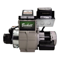
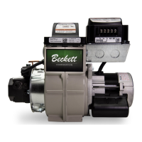
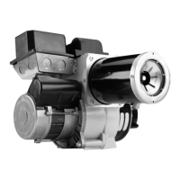
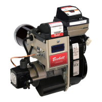
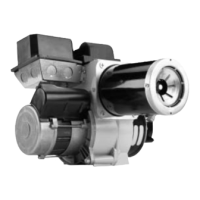
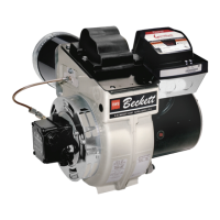
Compiles features and design differences between AF and AFG burner models.
Identifies the location of the burner's serial number and rating information label.
Warns against altering the original burner design, citing risks like voided warranties and safety hazards.
Details warnings about impaired burner performance and associated fire hazards.
Advises on preventing frozen plumbing and water damage during cold weather.
Lists fuels that should not be used with the burner to prevent explosions and damage.
Provides codes for matching air tubes to burner models and firing rates.
Details compliance requirements for installation in the US and Canada (NFPA, CSA).
Emphasizes matching fuel supply system components with the fuel used.
Stresses that installation, adjustment, and service must be done by qualified technicians.
Guides on inspecting the chimney or vent system for proper size and condition.
Recommends installing an insulated stainless steel liner due to flue gas condensation issues.
Details the need for adequate combustion and ventilation air supply for safe operation.
Specifies required clearances and combustion chamber dimensions for burner retrofitting.
Advises verifying the burner fuel unit compatibility with the oil supply system.
Warns about incorrect nozzles/flow rates causing combustion issues and fire hazards.
Explains nozzle flow rates based on pump pressure and required nozzle specifications.
Provides step-by-step instructions for installing or verifying the burner nozzle.
Guides on selecting the correct nozzle spray angle for different head types and desired flame patterns.
Details how to check and adjust electrode tip settings for proper ignition.
Outlines the steps for servicing or removing the nozzle line assembly.
Explains the purpose and use of the Low Firing Rate Baffle for specific applications.
Describes available mounting options for the burner to the appliance.
Provides guidance on air tube insertion depth and mounting pitch.
Explains the importance of the 'Z' dimension and how to check it for F heads.
Provides the procedure for adjusting the 'Z' dimension on F heads if incorrect.
Details checking and adjusting the 'Z' dimension for L1 and L2 head types.
Explains how to check and adjust the 'Z' dimension for V1 head types.
Provides a table for setting the V1 head adjusting plate based on firing rates.
Illustrates the correct placement and dimensions for mounting the burner in an appliance.
Warns about potential oil leaks and fire hazards during oil supply system installation.
Reaffirms the need for compatible fuel supply system components.
Prohibits the use of Teflon tape on fuel oil fittings due to potential damage.
Covers fuel line valves, filters, and typical system layout diagrams.
Warns against installing the bypass plug in one-pipe systems to prevent pump failure.
Directs users to appliance manufacturer diagrams for burner wiring when packaged.
Alerts users to the severe risk of electrical shock during wiring.
Provides guidance for wiring the burner when installed at a job site, referencing diagrams.
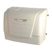
Details specific wiring considerations for burners equipped with covers.
Presents diagrams for interrupted and valve-on delay ignition wiring configurations.
Offers guidance on thermostat connections and potential polarity sensitivity issues.
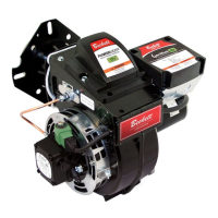
Introduces the Genisys Model 7505 control and its functions.
Highlights critical safety warnings related to the burner control, including fire and explosion hazards.
Explains the typical sequence of operation for the Genisys control system.
Details the steps for priming the oil pump and purging air from the system.
Explains how to measure cad cell resistance for flame detection verification.
Describes how to reset the control from restricted or hard lockout conditions.
Outlines the general process for starting up and checking the burner's operation.
Details tests for verifying the functionality of safety features like Safe Start and Flame Failure.
Guides on using instruments to adjust air settings for optimal combustion (CO2/O2 levels).
Emphasizes the need for annual professional servicing to prevent malfunction and hazards.
Provides instructions for shutting down the burner and proper long-term storage.
Lists specific parts related to air tubes, nozzle lines, and electrodes for replacement.
Fields for recording details about the burner installation.
Fields for documenting burner settings, pressures, and fuel type.
| Fuel Type | Oil |
|---|---|
| Frequency | 60 Hz |
| Flame Retention Head | Yes |
| Applications | Residential |
| Motor Voltage | 120 VAC |
| Input Range | 120 VAC |
| Ignition Type | High Voltage |
| Voltage | 120 VAC |
| Air Tube Lengths | 3-1/2", 4-1/2" |