BECKHOFF Drive Technology 4 Product description
AX5000 Version 6.2 23
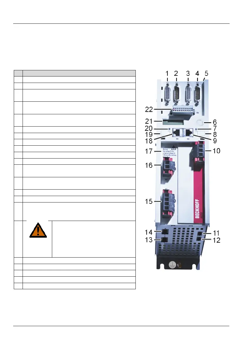
4.5 General overview (AX5101 – AX5112 and AX520x)
The servo drive shown below is a two-channel device. Components that are only available
for the second channel are identified in the item description.
X11 – feedback connection, encoder
X12 – feedback connection, resolver
X21 – feedback connection, encoder
channel B (only for two-channel unit)
X22 – feedback connection, resolver
channel B (only for two-channel unit)
X3x – optional slot for safety card
X4x – optional slot for expansion cards
Status LED for EtherCAT output
X05 – socket for EtherCAT output
X03 – power supply 24 V DC input
X14 – sensor for motor temperature and brake
X24 – sensor for motor temperature and brake
channel B (only for two-channel unit)
X23 – motor connection (U, V, W, PE)
channel B (only for two-channel unit)
X13 – motor connection (U, V, W, PE)
X01 – mains supply 100 – 480 V
(875 V DC voltage)
Connection for the external brake resistor
WARNING
875 V DC voltage at the DC link
terminals. Dangerous voltage may
be present for 5 minutes after the
device is switched off.
The device
is safe once the voltage has fallen
X04 – socket for EtherCAT input
Status LED for EtherCAT input
X06 – connection for digital inputs and outputs



 To Next Page