Do you have a question about the Beckhoff BK3100 and is the answer not in the manual?
Overview of Beckhoff Bus Couplers for PROFIBUS DP, including product numbers and features.
Details on safety regulations, exclusion of liability, personnel qualification, and hazard symbols used.
Detailed technical specifications for BK30x0, BK3100, BK3110, BK3120, and LC3100 Bus Couplers.
Guidelines for preventing electrostatic discharge damage to components during handling and assembly.
Information on supplying power to Bus Couplers and Bus Terminals (24 VDC operation).
Guidance on PROFIBUS cabling, including connector pin assignments and wire colors.
Special conditions for using Beckhoff components in potentially explosive areas (ATEX directive).
Specific requirements and marking for standard temperature range ATEX certified components.
Specific requirements and marking for extended temperature range ATEX certified components.
Explanation of configurable parameters within the Bus Coupler's UserPrmData for system settings.
Detailed guide on configuring Bus Couplers and their associated modules using DP configuration tools.
Process of generating CfgData from inserted modules in the DP configuration tool.
Steps for adding DP modules for Bus Coupler functions like PLC Interface and K-bus cycle counter.
Explanation of cyclic data exchange between Bus Coupler and PROFIBUS DP master.
How Bus Couplers manage process data, create internal assignment lists, and handle digital/analog signals.
Information on DPV1 for acyclic data transfer, including interface and slot number assignment.
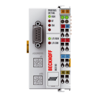
Explanation of the status LEDs on the Bus Coupler and their meanings for operation and errors.
Understanding DP diagnostic data (DiagData) and how it's reported to the master.
Detailed breakdown of DP standard diagnostic data offsets and their meanings.
Identifying and resolving errors occurring during the DP start-up phase, based on error codes.
| Product Name | BK3100 |
|---|---|
| Category | Adapter |
| Bus System | PROFIBUS DP |
| Supply Voltage | 24 V DC (-15%/+20%) |
| Current Consumption | Typically 70 mA |
| Protection Class | IP20 |
| Number of Channels | Varies with I/O modules |
| Data Transfer Rate | Up to 12 Mbit/s |
| Operating Temperature | 0 to 55 °C |
| Storage Temperature | -25 to 85 °C |
| Relative Humidity | 95% no condensation |
| Number of I/O Modules Connectable | Up to 64 modules |
| Temperature Range | 0°C to +55°C |