Do you have a question about the Beckhoff BK3150 and is the answer not in the manual?
Details safety regulations, exclusion of liability, personnel qualifications, and warning symbols.
Technical specifications for specific Bus Coupler models BK30x0, BK3100, BK3110, BK3120, LC3100.
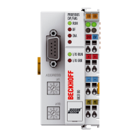
Technical specifications for the BK3150 Bus Coupler.
Technical specifications for BK35x0 Bus Couplers with optical fiber connection.
Guidelines for protecting devices from electrostatic discharge.
Details on supplying power to the Bus Coupler and Bus Terminals.
Special conditions for using components in potentially explosive areas.
Special conditions for ET components in potentially explosive areas.
Describes the self-test and operational states during Bus Coupler start-up.
Details available settings within the Bus Coupler's UserPrmData.
Guides for configuring the Bus Coupler and its modules.
Details how to add complex terminals in the DP configuration tool.
How to configure using TwinCAT automation software.
Guides for configuring with Siemens S7 controllers.
Details on cyclic data exchange in PROFIBUS DP.
Setting the K-bus cycle mode (FreeRun, Synchronous).
Explains the status indication provided by the Bus Coupler's LEDs.
Information on DP diagnostics and error reporting.
Details the structure and content of DP diagnostic data.
Identifies possible DP start-up errors based on error codes.
How the coupler reacts to PROFIBUS errors.
| Product Name | BK3150 |
|---|---|
| Category | Adapter |
| Manufacturer | Beckhoff |
| Fieldbus | PROFIBUS |
| Bus System | PROFIBUS DP |
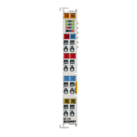
| Number of Bus Terminals | 64 |
| Operating Voltage | 24 V DC (-15%/+20%) |
| Current Supply | 24 V DC |
| Operating Temperature | 0°C to +55°C |
| Storage Temperature | -25°C to +85°C |
| Relative Humidity | 95%, no condensation |
| Protection Class | IP20 |
| Number of Terminals | 64 |
| Weight | approx. 160 g |
| Current Consumption | 70 mA |
| Data Transfer Rates | 9.6 kbit/s to 12 Mbit/s |