Mounting and wiring
CX8030 / CX8031 29Version: 1.6
1. Resistance between A and B at the start of the lead: approx. 110 Ohm
2. Resistance between A and B at the end of the lead: approx. 110 Ohm
3. Resistance between A at the start and A at the end of the lead: approx. 0 Ohm
4. Resistance between B at the start and B at the end of the lead: approx. 0 Ohm
5. Resistance between screen at the start and screen at the end of the lead: approx. 0 Ohm
If these measurements are successful, the cable is okay. If, in spite of this, bus malfunctions still occur, this
is usually a result of EMC interference. Observe the installation notes from the PROFIBUS User
Organization (www.profibus.com).
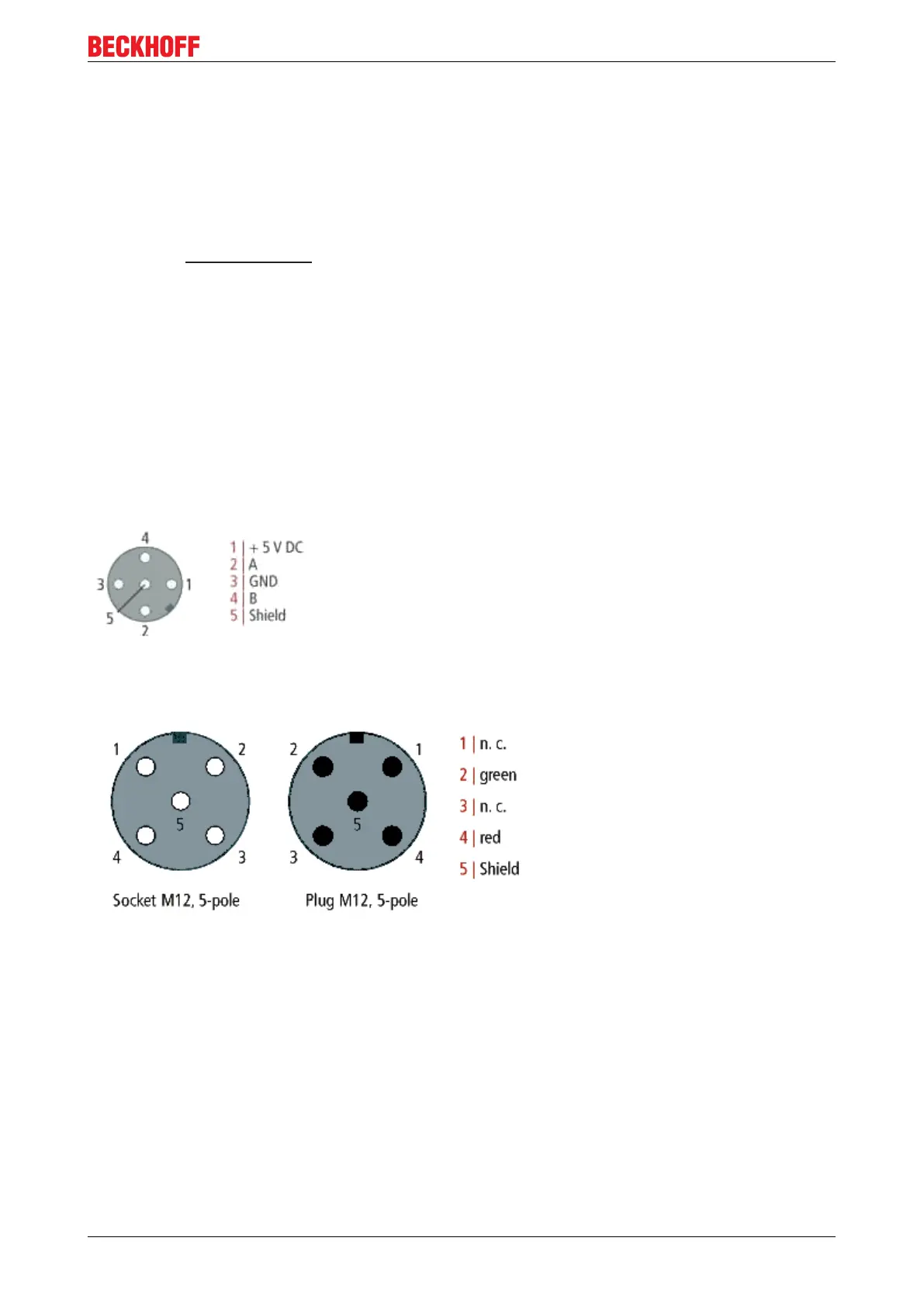
5.2.3.2 PROFIBUS Connection
M12 circular connector
The M12 socket is inverse coded, and has five pins. Pin 1 is 5 V
DC
and 3 is GND for the active termination
resistor. These must never be misused for other functions, as this can lead to destruction of the device.
Pin2 and pin4 are the PROFIBUS signals. These must never be swapped over, as this will prevent
communication. Pin5 is the shield, and this is capacitatively coupled to the Fieldbus Box chassis.
M12 socket pin assignment (-B310)
M12 socket/plug pin assignment (-B318)
Nine pole D-Sub
Pin 6 is 5 V
DC
und Pin 5 is GND for the active termination resistor. These must never be misused for other
functions, as this can lead to destruction of the device.
Pin3 and pin8 are the PROFIBUS signals. These must never be swapped over, as this will prevent
communication.