meters)
of
clearance at
the
rear and sides
of
the
Monitor
(see
Figure
3-1
).
As noted above,
don't
place the
Monitor
on long, plush carpet
or
spongy material where the
base
plate
might
come
in
contact
with
the
mounting
surface and
restrict the air circulation. Never
allow
paper
or
other
material
to
be
stored under
the
ter-
minal where
it
may cover fan screen and
re-
strict
air
flow
.
Care
must
be
used
to
ensure
that
the fan screen does
not
become
bent
and interfere
with
the fan.
3.5.2 Power Connection
It
is
rernrnr::enrlcd
that
instrument
panels
and cabinets
he
grounded
to
protect
operating
and servicing personnel. The SUPER BEE
is
shipped
with
a shielded three-conductor power
cord
which, when plugged
into
an
appropriate
outlet,
grounds the
instrument
through the
offset pin.
To
operate the SUPER BEE
from
a
two-contact
outlet,
us~
a three-conductor
to
two-conductor
adapter. Preserve the safety
feature
by
grounding the adapter pigtail lead.
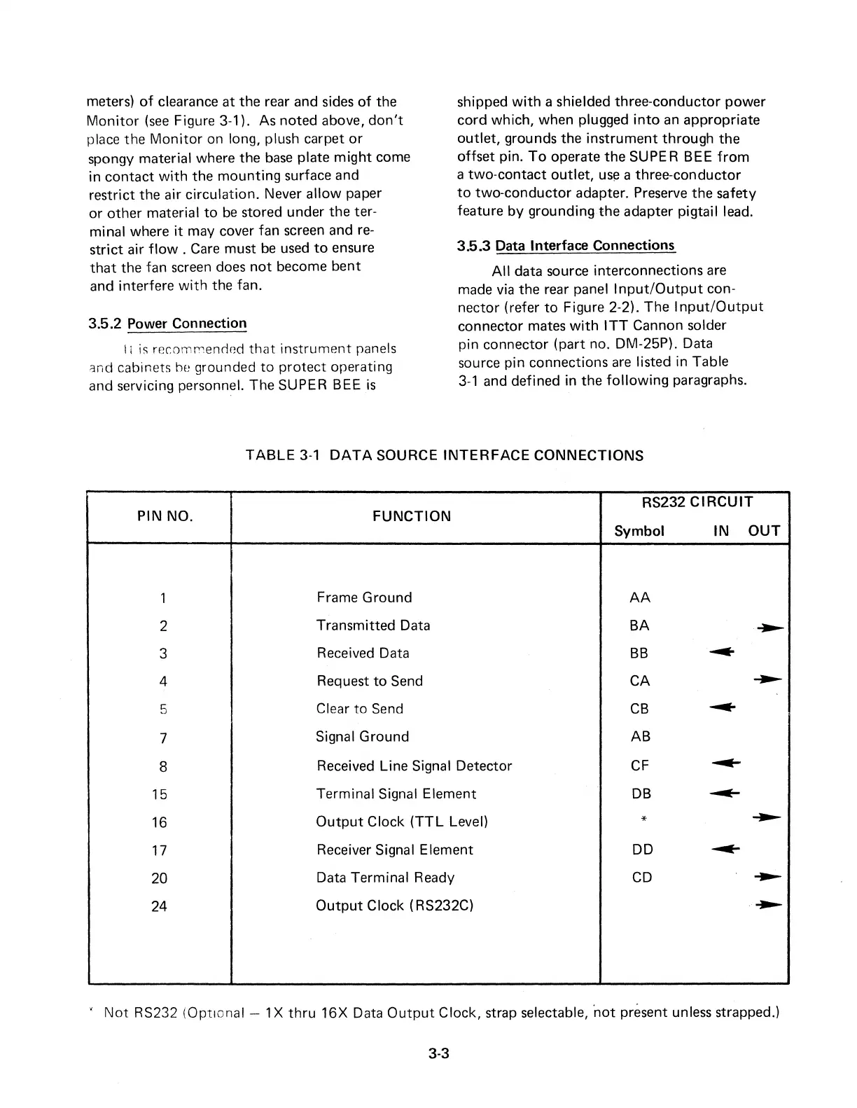
3.5.3
Data Interface Connections
All
data source interconnections
are
made
via
the rear panel
Input/Output
con-
nector (refer
to
Figure 2-2).
The
Input/Output
connector mates
with
ITT
Cannon solder
pin connector
(part
no. DM-25P). Data
source pin connections
are
listed in Table
3-1
and defined in the
following
paragraphs.
TABLE
3-1
DATA
SOURCE
INTERFACE
CONNECTIONS
RS232
CIRCUIT
PIN NO.
FUNCTION
Symbol
IN
OUT
1
Frame Ground
AA
2
Transmitted Data
BA
~
3
Received Data
BB
~
4
Request
to
Send CA
~
5
Clear
to
Send
CB
---
7
Signal Ground AB
8
Received Line Signal Detector
CF
---
15
Terminal Signal Element
DB
~
16
Output
Clock
(TTL
Level)
*
~
17
Receiver Signal Element DD
---
20
Data Terminal Ready
CD
---
24
Output
Clock (RS232C)
~
'
Not
RS232 (Optional - 1 X
thru
16X
Data
Output
Clock, strap selectable, ·not present unless strapped.)
3-3