20
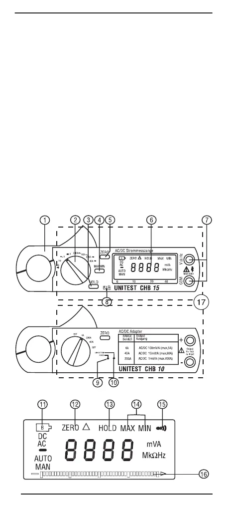
3.0 Controls and Connections
1. Induction coil (clamp)
2. Selector switch, for type of measurement
3. Data hold button, to memorise reading
4. MIN/MAX value function
5. Zero setting
6. Digital display
7. Input socket, for measuring voltage and resistance, and for
continuity and diode testing
8. On/Off-switch (only UNITEST Clamp Meter CHB 15)
9. LED-ON/OFF-indicator (only UNITEST Clamp Adapter CHB 10)
10. LED for Battery-indicator
(only UNITEST Clamp Adapter CHB 10)
11. Battery display
12. Zero/Relativ value display
13. HOLD-display
14. MIN/MAX-value display
15. Continuity symbol
16. Analog Bargraph
17. Hand-hold area incl. Barrier
PTDB93468-05.qxd 14.12.2005 9:41 Uhr Seite 20