17
4.3 Rear control elements
17 181920
21
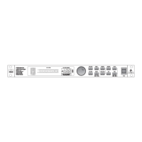
Fig. 4.4: Connectors and control elements on the rear of the FEEDBACK DESTROYER
17
Use the
Operating Level
switch to adapt the FEEDBACK DESTROYER to different operating levels.
You can select a -10 dBV semi-pro level used for home recording and a +4 dBu level used in profes-
sional studios. The level indicators on the front are adapted automatically to the selected nominal
level, i.e. an optimum operating range of the meters will always be assured.
18
The FEEDBACK DESTROYER was designed for operation with unbalanced mono phone jacks (6.3
mm). Each audio channel (left/right) has a phone jack for incoming signals. If you only want to use the
device with a mono input, please use the left input.
19
Also the two outputs of the FEEDBACK DESTROYER have one phone jack for each audio channel.
20
The FEEDBACK DESTROYER features extensive MIDI implementation. In addition to the standard
MIDI IN
and
MIDI OUT
connectors, you can loop through MIDI signal by using the
MIDI THRU
jack.
21
Use the enclosed power cord and
ICE mains connector
to connect the FEEDBACK DESTROYER to
the mains power supply.
4. CONTROL ELEMENTS