EasyManua.ls Logo

Behringer Filter Machine FM600 User Manual

Behringer Filter Machine FM600
3 pages
To Next Page IconTo Next Page
Page #1 background imageLoading...
Page #1 background image
FILTER MACHINE FM600
Ultimate Filter Modeling Eects Pedal
Thank you for showing your condence in us by purchasing the BEHRINGER FILTER MACHINE FM600.
This Filter Modeler delivers the whole range from funky auto-wah, twin, band-pass to swirling low-pass
lter eects—at the touch of a footswitch. Discover the world of moving lters and take o with sounds
you have never heard before.
1. Controls
(1) The FILTER switch is used to select one of three lter types (BP=Band Pass, TF=Twin Filter
band pass, LP=Low Pass), which deliver completely dierent sounds. Cut-o and center
frequencies respond to the dynamics of your playing.
(2) The SENS knob determines the sensitivity of the lter and hence the level at which the lter
frequency modulation starts to work.
(3) The PEAK knob is used to dene the shape of the lter from narrow to wide.
(4) The POL switch determines whether the lter frequency moves up to higher frequencies (UP)
or down to lower frequencies (DOWN) according to the dynamics of your playing.
(5) With the RANGE knob, you can alter the travel range of the lter frequency.
(6) The ON/BATT LED lights up, as soon as the eect is activated. Furthermore, you can check the
status of the battery.
(7) The footswitch is used for switching the eect on/o.
(8) The ¼" TS connector (IN) connects to your instrument.
(9) The ¼" TS connector (OUT) sends the signal to your amp/combo.
Use the DC IN connection at the front of the unit to plug in a 9 V power supply (not included).
The BATTERY COMPARTMENT is located underneath the pedal cover. To install or replace the
9 V battery (not included), press the hinges with a ballpen and remove the pedal cover. Be careful not
to scratch the unit.
(6)
(2)
(1)
(9)
(8)
(3)
(7)
(4)
(5)
Question and Answer IconNeed help?

Do you have a question about the Behringer Filter Machine FM600 and is the answer not in the manual?

Behringer Filter Machine FM600 Specifications

Ports & interfaces IconPorts & interfaces
input connector type1/4" TS
input impedance500 kΩ
output connector type1/4" TS
output impedance1 kΩ
power connector type2 mm DC jack, negative center
Power IconPower
power supply voltage9 V
power supply current100 mA
power consumption60 mA
battery type9 V type 6LR61
USA/Canada voltage120 V~, 60 Hz
China/Korea voltage220 V~, 50/60 Hz
Europe/U.K./Australia voltage230 V~, 50 Hz
Japan voltage100 V~, 50 - 60 Hz
export model voltage120/230 V~, 50 - 60 Hz
Weight and Dimensions IconWeight and Dimensions
height54 mm (2 1/8")
width70 mm (2 3/4")
depth123 mm (4 4/5")
weight0.33 kg (0.73 lbs)

Summary

Controls Overview

FILTER Switch

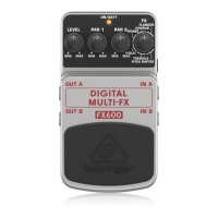
Selects filter type (BP, TF, LP) responding to playing dynamics.

SENS Knob

Adjusts filter sensitivity and modulation start level.

PEAK Knob

Defines filter shape from narrow to wide.

POL Switch

Determines filter frequency movement direction (UP/DOWN).

RANGE Knob

Alters the travel range of the filter frequency.

ON/BATT LED

Indicates effect activation and battery status.

Footswitch

Switches the effect on and off.

Instrument Input (IN)

¼" TS connector for instrument signal input.

Amplifier Output (OUT)

¼" TS connector for signal to amplifier.

DC IN Power Connection

Front connection for 9 V power supply.

Battery Compartment

Located under pedal cover for 9 V battery.

Safety Instructions

General Precautions

Avoid water, heat, use authorized accessories, and do not service yourself.

Interference Handling

Turn down volume and briefly disconnect input to resolve external interferences.

Specifications

Input/Output Details

Details connector types and impedance for input and output.

Power Supply Requirements

Specifies 9V, 100mA regulated power and AC adapter compatibility.

Physical Dimensions and Weight

Provides physical size and weight of the FM600 pedal.

FCC Compliance Information

FCC Statement

Confirms compliance with FCC Part 15 limits for digital devices.

Interference Correction Measures

Lists steps to correct harmful interference to radio or television reception.

Operational Conditions

States device must not cause harmful interference and accept received interference.

Modification Warning

Warns that unauthorized modifications void user authority.

Related product manuals