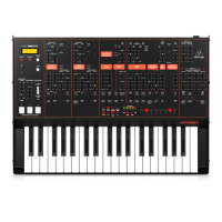
9 NEUTRON User Manual
(71) ATT2 IN – Attenuator 2 signal input.
(72) SLEW IN – Slew signal input.
(73) SUM1(A) – SUM 1 rst signal input. See 98.
(74) SUM1(B) – SUM1 second signal input. See 98.
(75) SUM2(A) – SUM 2 rst signal input. See 99.
(76) SUM2(B) – SUM 2 second signal input. See 99.
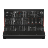
Output Patch Bay Section
(77) OSC 1 – Output of Oscillator 1.
(78) OSC 2 – Output of Oscillator 2.
(79) OSC Mix – Output of OSC 1/2 mix.
(80) VCF 1 – Main output of the lter.
(81) VCF 2 – Alternate output of the lter.
(82) OVERDRIVE – Overdrive output signal.
(83) VCA – Voltage Controlled Amplier output signal.
(84) OUTPUT – Main output signal, post delay.
(85) NOISE – Output of the white noise generator.
(86) ENV1 – Envelope 1 output.
(87) ENV2 – Envelope 2 output.
(88) INVERT – Inverted version of signal applied to INVERT IN. See 48.
(89) LFO – Output of the Bipolar LFO (-5 V to +5 V).
(90) LFO UNI – Output of the Unipolar LFO (0V to +5 V).
(91) S&H – Sample and Hold output signal.
(92) MULT 1 – Duplicate of signal applied to MULT IN. See 68.
(93) MULT 2 – Duplicate of signal applied to MULT IN. See 68.
(94) MIDI GATE – MIDI gate output.
(95) ATT1 – Output of Attenuator 1.
(96) ATT2 – Output of Attenuator 2.
(97) SLEW – Output of Slew.
(98) SUM1 – Summation of SUM 1(A+B).
(99) SUM2 – Summation of SUM 2(A+B).
(100) ASSIGN – Assignable output. See User Congurable Options & Features.
(77) (78) (79)
(80) (81) (82)
(83) (84) (85)
(86) (87) (88)
(89) (90) (91)
(92) (93) (94)
(95) (96) (97)
(98) (99) (100)
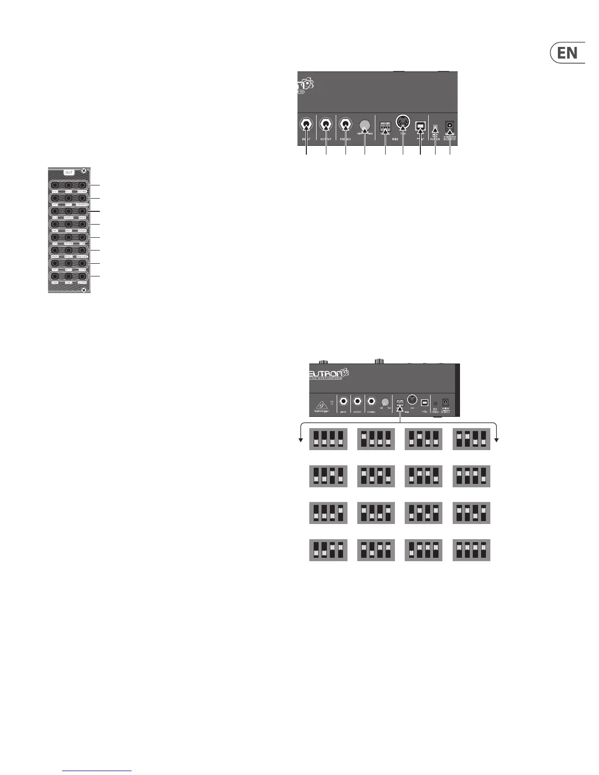
3.2.2 Rear Panel
(101) INPUT – Mono unbalanced audio input using a ¼" (6.35 mm) jack cable for
processing external sound sources.
(102) OUTPUT – Connect to a mixer or audio interface using a ¼" (6.35 mm) mono
jack cable. Remember to turn your monitors/loudspeakers on last when
turning on your system and turn your monitors/loudspeakers o rst when
turning your system o.
(103) PHONES – ¼" (6.35 mm) jack connection to plug headphones in.
(104) PHONES LEVEL – Ensure the volume control is at minimum when putting
on headphones or when turning the synthesizer on or o.
(105) MIDI CHANNEL SELECTION.
Move the four dip switches to select the incoming MIDI channel for the
synthesizer.
(106) MIDI THRU – The 5-pin MIDI DIN connector is used to pass through MIDI
data received at the MIDI INPUT.
(107) USB PORT – Connects to a computer via standard USB cable. The Neutron
will display in your DAW as a class-compliant USB MIDI device, capable of
sending and receiving MIDI information.
(108) POWER SWITCH – Turns the synthesizer on and o. Make all audio
connections before powering on.
(109) POWER INPUT – Connect the supplied power supply only.
(101) (102) (103) (104) (105) (106) (107) (108)(109)
MIDI CHANNEL DIP SWITCH SETTINGS
1 2 3 4
5 6 7 8
9 10 11 12
13 14 15 16