Do you have a question about the Behringer 112 DUAL VCO and is the answer not in the manual?
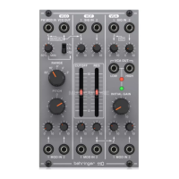
Accepts a voltage from another module to control the pulse width.
Sends the VCO signal to one or two sources via 3.5 mm TS cables.
Selects pulse, triangle, or sawtooth waveforms for the VCO.
Adjusts pulse width modulation based on voltage at PW MOD IN.
Sets ratio between upper and lower portions of the pulse wave.
Sends a synchronization signal via 3.5 mm TS cable.
Sets the pitch range of the VCO in octave steps.
Accepts a synchronization signal via 3.5 mm TS cable.
Determines the accuracy of synchronization.
Fine tunes the pitch.
Adjusts the signal level connected to the associated MOD IN jack.
Accepts voltages that control or modulate the VCO pitch.
Turn the power supply or rack case power off and disconnect the power cable.
Insert the 16-pin connector into the power supply or rack case socket.
Insert the 10-pin connector into the socket on the back of the module.
Mount the module in a case and turn on the power supply.
Details on input type, impedance, and maximum input level.
Details on output type, impedance, maximum level, and frequency ranges.
Details on input type, impedance, maximum input level, and minimum trigger.
Details on output type, impedance, and maximum output level.
Details on input type, impedance, and CV range.
Details on PW level, PW manual, Waveform, Range, Pitch, Weak/strong, Mod level.
Details on power supply and current draw.
Details on module dimensions, rack units, and weight.
| Oscillators | 2 |
|---|---|
| PWM | Yes |
| Sync | Hard Sync |
| Voltage Control | 1V/Octave |
| Width | 16 HP |
| Type | Analog |
| Waveforms | Sawtooth, Triangle |
| Modulation | PWM, FM |
| CV Inputs | PWM, Sync |
| Controls | Frequency, Fine Tune, PWM |
| Current Draw | 60 mA +12V, 50 mA -12V |