6 150 RING MOD/NOISE/S&H/LFO Quick Start Guide 7
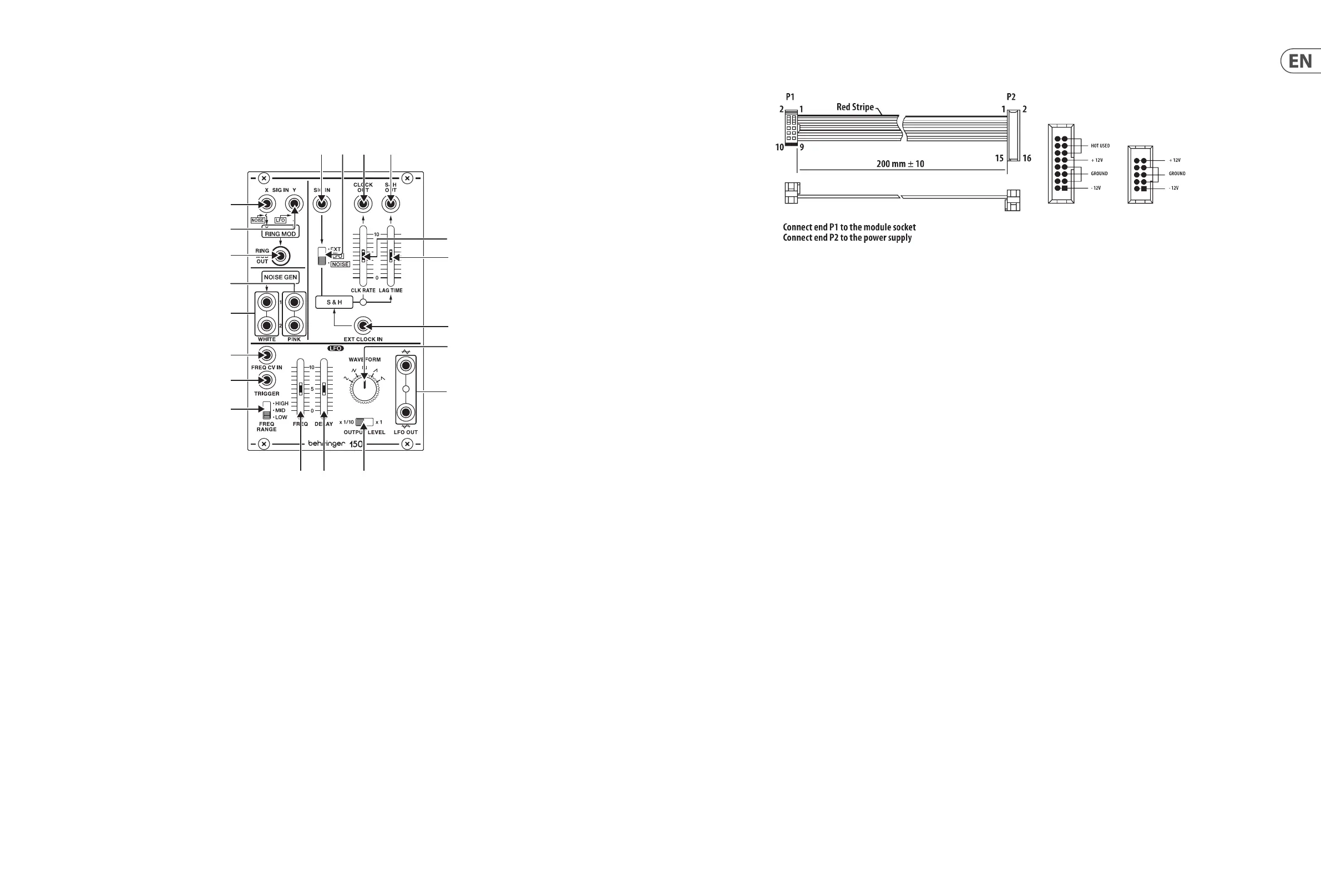
150 RING MOD/NOISE/S&H/LFO Controls
1. EXT SIG X/NOISE
–
jack routes audio signals or noise into the ring modulator.
The audio signal or noise coming in through the EXT SIG X/NOISE jack is combined
with and modulated by the carrier signal routed into the EXT SIG Y/LFO jack.
2. EXT SIG Y/LFO
–
jack routes the carrier signal into the ring modulator. The carrier
signal can be in the audio range, such as a 500 Hz sine wave, or a signal from Low
Frequency Oscillator (LFO).
3. R.M OUT
–
jack sends out the nal ring modulator signal.
4. PINK
–
output jacks oer dual white pink noise outputs for use other modules.
5. WHITE
–
output jacks oer dual white noise outputs for use with other modules.
6. EXT SIG
–
input jack routes external signals into the S&H circuit for processing.
Use the EXT/LFO/NOISE switch to optimize the EXT SIG input for dierent types
of signals.
7. EXT/LFO/NOISE
–
sliding switch optimizes the EXT SIG for use with control signals
(EXT), signals from a Low Frequency Oscillator (LFO) or noise signals (NOISE).
8. CLOCK OUT
–
jack sends out a clock signal generated inside the S&H circuit.
9. CLOCK RATE
–
slider controls the internal clock signal's rate before the clock signal
is routed out through the CLOCK OUT jack.
10. S&H OUT
–
jack sends out the nal S&H (Sample & Hold) signal over cables with
3.5 mm TS connectors.
11. LAG TIME
–
slider can be used to smooth out the changes between control voltage
values as the slider is raised, similar to a portamento or glide eect on a keyboard.
12. EXT CLOCK IN
–
input jack routes an external clock signal into the S&H circuit.
13. WAVEFORM
–
knob selects between sine, triangle, square, ramp and sawtooth
waveforms for the LFO.
14. FREQ RANGE
–
sliding switch selects between high (H), mid (M) and low (L)
frequency ranges.
15. TRIGGER
–
jack allows a control voltage to trigger the LFO waveform by resetting
the amplitude to 0. The waveform then returns to the original amplitude at a rate
set by the DELAY slider.
16. FREQ
–
slider ne-adjusts the LFO frequency within the range chosen by the FREQ
RANGE switch.
17. DELAY
–
slider controls the amount of time that elapses between the beginning of
a new note and the LFO's amplitude peak.
18. FREQ CV IN
–
input jack allows a control voltage to control the LFO frequency in
place of the FREQ slider.
19. OUTPUT LEVEL
–
sliding switch selects between a full-strength LFO output signal
(x1 setting) and a 1/10th-strength signal (x 1/10 setting).
20. LFO OUT
–
output jacks oer dual LFO outputs for use with cables with 3.5 mm
TS connectors.
(6) (7) (8) (10)
18)
15)
14)
(20
(12
(13
(11
(EN)
Controls
Power Connection
The 150 RING MOD / NOISE / S&H / LFO module comes with the required power
cable for connecting to a standard Eurorack power supply system. Follow these
steps to connect power to the module. It is easier to make these connections
before the module has been mounted into a rack case.
1. Turn the power supply or rack case power o and disconnect the power cable.
2. Insert the 16-pin connector on the power cable into the socket on the power
supply or rack case. The connector has a tab that will align with the gap in the
socket, so it cannot be inserted incorrectly. If the power supply does not have
a keyed socket, be sure to orient pin 1 (-12 V) with the red stripe on the cable.
3. Insert the 10-pin connector into the socket on the back of the module.
The connector has a tab that will align with the socket for correct orientation.
4. After both ends of the power cable have been securely attached, you may
mount the module in a case and turn on the power supply.
Installation
The necessary screws are included with the module for mounting in a Eurorack
case. Connect the power cable before mounting.
Depending on the rack case, there may be a series of xed holes spaced 2 HP
apart along the length of the case, or a track that allows individual threaded
plates to slide along the length of the case. The free-moving threaded plates
allow precise positioning of the module, but each plate should be positioned in
the approximate relation to the mounting holes in your module before attaching
the screws.
Hold the module against the Eurorack rails so that each of the mounting holes
are aligned with a threaded rail or threaded plate. Attach the screws part way
to start, which will allow small adjustments to the positioning while you get
them all aligned. After the nal position has been established, tighten the
screws down.
 Loading...