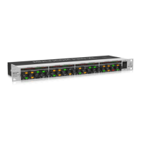
1. The DCX2496(LE) features 6-segment LED displays (plus CLIP and MUTE LED) for precise level adjustment of
input signals A-B or A-C.
2. If the input stage is overdriven, the CLIP LED will indicate that the signal is distorting.
3. The bottom LED (#8) is the MUTE LED (red), which illuminates when the respective input is muted.
4. These are the input channel buttons, which allow you to activate specific functions from the selected menus
(e.g. MUTE). Additionally, you can use these buttons to call up the IN A/B/C menus.
5. The DISPLAY shows all the menus available for preset editing.
6. Use these buttons to call up the DCX2496(LE)’s menus (e.g. SETUP, RECALL, etc.). The only exception is the
COMPARE button, which allows you to compare the edits made with the previously selected presets. When
COMPARE is active, no value changes can be entered.
7. The PAGE buttons select single pages from one menu.
8. Individual parameters can be selected with the PARAM buttons.
9. The data wheel allows you to edit the selected parameters.
10. With the OK and CANCEL buttons you can either confirm or cancel any settings made.
11. Outputs 1-6 each have a 5-segment LED display (plus MUTE, CLIP and LIMIT LED) showing the respective
output levels.
12. Like the input stages, the output stages should not be overdriven, i.e. the CLIP LED should not illuminate.
13. The LIMIT LED illuminates when the limiter for the corresponding output has been activated and is operating.
14. The bottom LED indicator (#8) is the MUTE LED, which illuminates as soon as the corresponding output is
muted.

 Loading...