U-PHORIA UMC404HD/UMC204HD/UMC202HD/UMC22/UM2
Quick Start Guide25
24
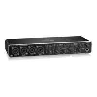
(15) OUTPUT (UM2 / UMC22 / UMC202HD) /
MAIN OUT (UMC204HD & UMC404HD)
knob adjusts the output level at the
1(L) & 2(R) OUTPUTS (UM2 / UMC22/
UMC202HD) or the L & R MAIN OUT
(UMC204HD & UMC404HD).
(16) POWER LED indicates that the unit is
poweredon.
(17) +48 V LED indicates that +48 V phantom
power isengaged.
(18) output. Connect to headphones for
playback andmixing.
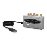
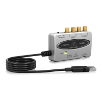
(19) USB type B connector. Connect to a
computer via thisconnector.
(20) +48 V ON/OFF selector engages
+48 V phantom power
(required for professional studio
condensermicrophones).
(21) 1(L) & 2(R) OUTPUTS (UM2 / UMC22
/ UMC202HD) / L & R MAIN OUT
(UMC204HD & UMC404HD) connect to
powered studio monitors for playback
andmixing.
(22) DC IN (UMC404HD) connect to the mains
via the included power adapter.
(23) MIDI IN/OUT (UMC204HD & UMC404HD)
connect to external MIDI controllers and
modules via theseconnectors.
(24) PLAYBACK OUTPUTS A 1 & 2 / B 3 &4
(UMC204HD) / PLAYBACK OUTPUTS A
1/L & 2/R / B 3/L & 4/R (UMC404HD)
connect to external speakers for additional
monitoring options.
(25) INSERTS 1 & 2 (UMC204
HD
) / 1 – 4
(UMC404
HD
) connect to external signal
processing devices via theseconnectors.
(EN) Step 2: Controls
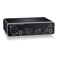
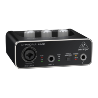
(1) MIC/LINE 1 (UM2 & UMC22) / INPUT 1
& 2 (UMC202HD & UMC204HD) / INPUT
1 – 4 (UMC404HD) combination XLR/
¼" connectors. Connect microphones,
instruments or line level audio sources to
theseconnectors.
(2) INST 2 (UM2 & UMC22) ¼" connector.
Connect instrument and audio sources to
this connector.
(3) LINE / INST (UMC202HD / UMC204HD
/ UMC404HD) selector designates line
level or instrument level input source at
combination XLR/¼"connector(s).
(4) PAD (UMC202HD / UMC204HD /
UMC404HD) selector reduces input level
for connected sources whenengaged.
(5) DIRECT MONITOR (UM2 / UMC22 /
UMC202HD) selector activates direct
monitoring of input signals with zero
latency (no delay) whenengaged.
(6) STEREO/MONO (UMC204HD &
UMC404HD) selector activates mono
monitoring of audio signals connected
to INPUT 1 and INPUT 2 (UMC204HD) or
INPUTS 1 – 4 (UMC404HD) when engaged.
(7) MIX (UMC204HD & UMC404HD) knob
adjusts the level of input signal to playback
1-2 signal at the MAIN OUT and at the
output (ifMONITOR A is selected for the
output).
(8) MONITOR A/B (UMC204HD & UMC404HD)
selector designates output channels
3 & 4 at the output when engaged.
(9) PHONES (UMC202HD / UMC204HD /
UMC404HD) knob adjusts the output level
at the (headphones)output.
(10) SIG LED indicates that an audio signal is
present in the channel.
(11) MIC/LINE GAIN 1 (UM2) / GAIN 1 &2
(UMC22 / UMC202HD /UMC204HD)
GAIN 1 – 4 (UMC404HD) knob adjusts
the input level at MIC/LINE 1 (UM2), MIC/
LINE 1 & INST 2 (UMC22), INPUT 1 & 2
(UMC202HD & UMC204HD), or INPUT 1 – 4
(UMC404HD).
(12) INST GAIN 2 (UM2) knob adjusts the input
level at the INST 2 input.
(13) CLIP LED indicates that the audio
signal in the channel is too loud.
Turn the corresponding GAIN knob
counter-clockwise until the CLIP LED
nolongerilluminates.
(14) MIDI IN/OUT LEDs (UMC204HD &
UMC404HD) indicate MIDI signal activity.
U-PHORIA UMC404HD/UMC204HD/UMC202HD/UMC22/UM2 Controls