3. Make sure that the mounting surface of the cutout is smooth and cleaned from any burrs or
debris.
4. Install the HMI panel into the cutout.
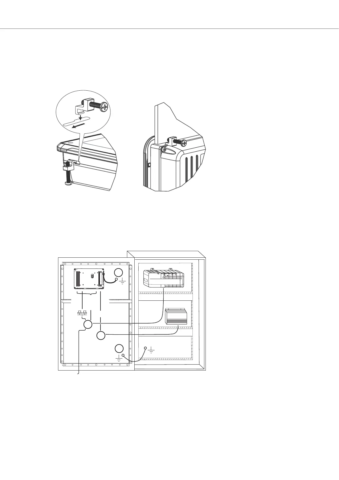
5. Secure the HMI panel in position, using all the fastening holes and the provided brackets and
screws.
Tighten the screws to 0.5 - 1.0 Nm.
6. In cases where the front panel seal (IP54 or greater, NEMA-4X) is critical, use a torque wrench to
ensure all screws are torqued within the specification above.
7. Connect the cables in the specified order, according to the following drawing and steps.
24V DC
RS232/
RS422/
RS485
24V DC
A
D
Controller
Power
B
Ethernet
C
The image is illustrative only and may differ slightly from the actual panel.
• Connect cable A.
• Connect cable B, using 14-20 AWG (2.08–0.52 mm
2
), 180–220 N-cm torque.
• Connect cable C.
• Connect cable D. The recommended cross-section of the cable is 1.5 mm
2
.
Installation
2023-09 12 Beijer Electronics, MAEN220
 Loading...