6. HMI Panel Drawings
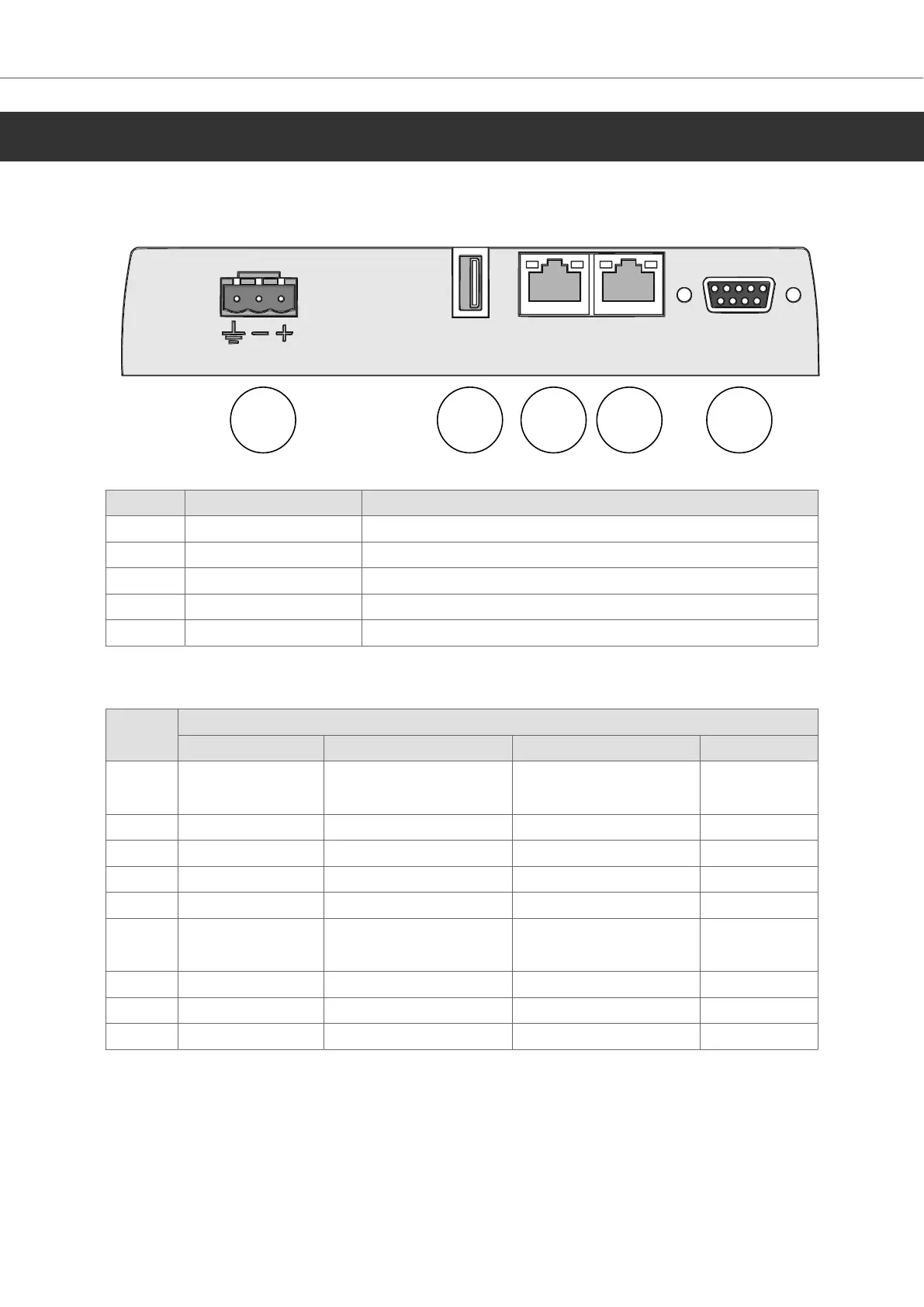
6.1. Connectors
Pos Connector Description
1 Power supply +24 V DC (18–32 V DC)
2 USB USB Host 2.0, max output current 500mA
3 LAN A 1×10/100 Base-T (shielded RJ45)
4 LAN B 1×10/100 Base-T (shielded RJ45)
5 COM Serial communication port
6.1.1. Communication Ports
Pin D-sub-9, female
COM 1 COM 2 COM 3 CAN 1
1 RS-422 Tx+
RS-485 Tx+/Rx+
CAN 1-H
2 RS-232 RxD
3 RS-232 TxD
4 RS-422 Rx+ RS-485 Tx+/Rx+
5 GND GND GND GND
6 RS-422 Tx-
RS-485 Tx-/Rx-
CAN 1-L
7 RS-232 RTS
8 RS-232 CTS
9 RS-422 RX- RS-485 Tx-/Rx-
The connector supports up to three independent communication channels and can be configured for
RS-232 and RS-422 or 2x RS-485 or 1x CAN.
HMI Panel Drawings
2023-09 18 Beijer Electronics, MAEN220
 Loading...