3
1. DESCRIPTION
These panel mounting, intrinsically safe digital
indicators display the current flowing in a 4/20mA
loop in engineering units. They are loop powered
but only introduce a 1.2V drop, which allows them
to be installed into almost any 4/20mA current
loop. No additional power supply or battery is
required.
The four models are electrically similar, but have
different size displays and enclosures.
Model Display Bezel size
BA307E 4 digits 15mm high 96 x 48mm
BA327E 5 digits 11mm high 96 x 48mm
and bargraph.
BA308E 4 digits 34mm high 144 x 72mm
BA328E 5 digits 29mm high 144 x 72mm
and bargraph.
This instruction manual supplements the
instruction sheet supplied with each instrument.
The main application of all the models is to display
a measured variable or control signal in a
hazardous process area. The zero and span of
the display are independently adjustable so that
the indicator can be calibrated to display any
variable represented by the 4/20mA current, e.g.
temperature, flow, pressure or level.
All the models have been certified intrinsically safe
for use in gas and dust hazardous areas by
Notified Body Intertek Testing and Certification Ltd
and comply with the European ATEX Directive
94/9/EC. The EC-Type Examination certificate
specifies that under fault conditions the output
voltage, current and power at the 4/20mA input
terminals will not exceed those specified for simple
apparatus in Clause 5.7 of EN 60079-11, which
simplifies installation and documentation.
For international applications all models have
IECEx certification which is described in
Appendix 2.
For applications in the USA and Canada all models
have FM and cFM certification, see Appendix 3.
2. OPERATION
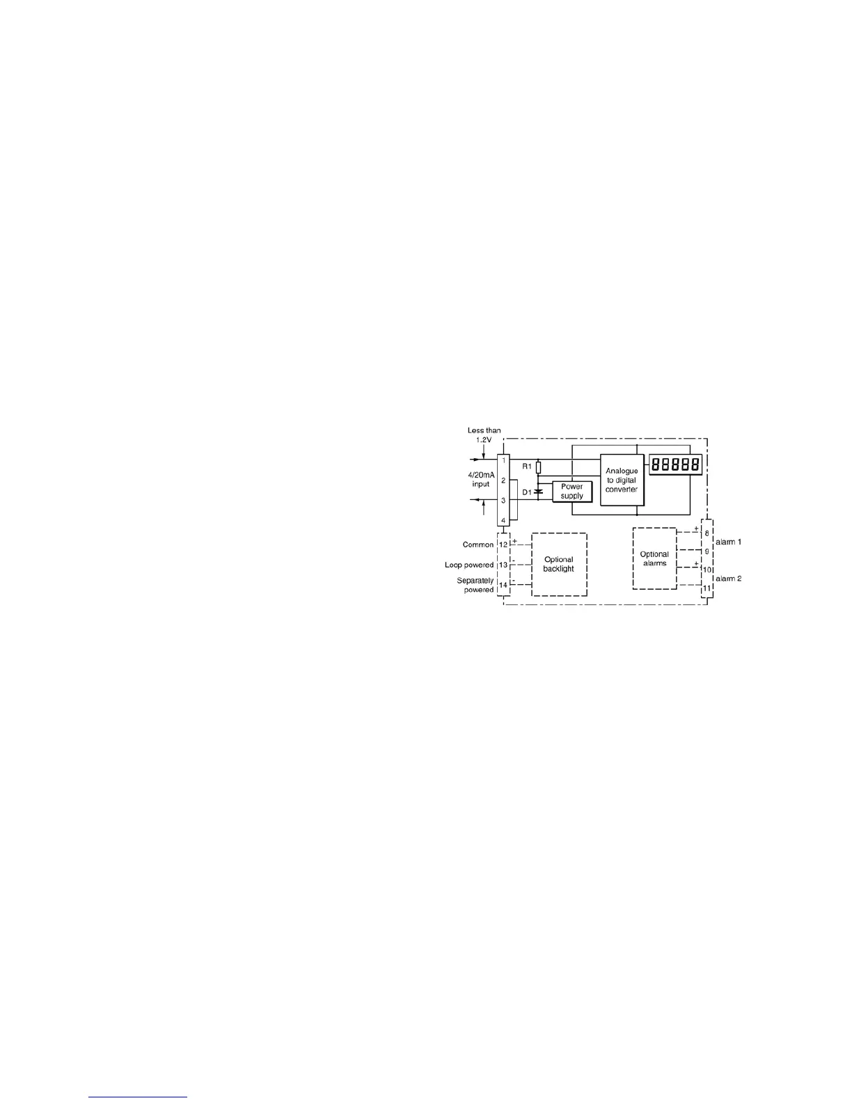
Fig 1 shows a simplified block diagram of all the
models. The 4/20mA input current flows through
resistor R1 and forward biased diode D1. The
voltage developed across D1, which is relatively
constant, is multiplied by a switch mode power
supply and used to power the instrument. The
voltage developed across R1, which is proportional
to the 4/20mA input current, provides the input
signal for the analogue to digital converter.
Each time a 4/20mA current is applied to the
instrument, initialisation is performed during which
all segments of the display are activated, after five
seconds the instrument displays the input current
using the calibration information stored in the
instrument memory. If the loop current is too low
to power the instrument the indicator will display
the error message ‘LPLo’.
Fig 1 Indicator block diagram