8
5.3 Installation Procedure
a. Cut the specified aperture in the panel. To
achieve an IP66 seal between the instrument
enclosure and the instrument panel the
aperture must have the tighter tolerances
specified in Fig 4A and 4B.
b. Slide the gasket over the body of the
indicator before inserting the instrument into
the panel aperture.
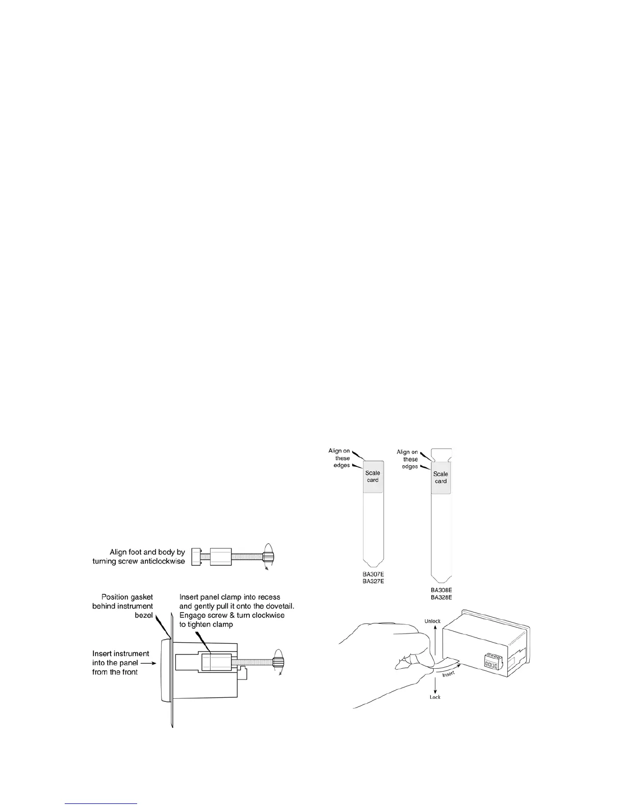
c. Firstly ensure that all the panel mounting
clamps are closed by turning the knurled
screws fully anti clockwise until the two pips
in the clamp foot align with holes in the clamp
body.
d. Place a clamp in the recess on each side of
the indicator, pulling gently to slide it onto the
dovetail as shown in Fig 5. Push the knurled
screw slightly forward to engage the thread
and tighten by turning clockwise until it is just
finger tight. When both clamps are fitted
ensure that the gasket behind the front panel
bezel is correctly positioned before fully
tightening the clamps to secure the
instrument. The maximum recommended
clamp tightening torque is 22cNm (1.95 lbf in)
which is approximately equvalent to finger-
tight plus one half turn. Do not over tighten.
e. Four panel mounting clamps are required to
achieve an IP66 seal between a BA308E and
BA328E indicator and the instrument panel.
f. Connect the panel wiring to the rear terminal
block(s) as shown in Figs 4A and 4B. To
simplify installation, the terminals are
removable so that the panel wiring can be
completed before the instrument is installed.
Fig 5 Fitting panel mounting clamps
5.4 Scale card
The indicator’s units of measurement are shown
on a printed scale card in a window at the right
hand side of the display. The scale card is
mounted on a flexible strip that is inserted into a
slot at the rear of the instrument as shown in Fig 6.
Thus the scale card can easily be changed without
removing the indicator from the panel or opening
the instrument enclosure.
New indicators are supplied with a printed scale
card showing the requested units of measurement,
if this information is not supplied when the indicator
is ordered a blank card will be fitted.
A pack of self-adhesive scale cards printed with
common units of measurement is available as an
accessory from BEKA associates. Custom printed
scale cards can also be supplied.
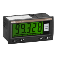
To change a scale card, unclip the protruding end
of the flexible strip by gently pushing it upwards
and pulling it out of the enclosure. Peel the
existing scale card from the flexible strip and
replace it with a new printed card, which should be
aligned as shown below. Do not fit a new scale
card on top of an existing card.
Install the new scale card by gently pushing the
flexible strip into the slot at the rear of the indicator,
when it reaches the internal end-stop secure it by
pushing the end of the flexible strip downwards so
that the tapered section is held by the rear panel.
Align the self-
adhesive printed
scale card onto
the flexible strip
and insert the strip
into the indicator
as shown below.
Fig 6 Inserting flexible strip carrying scale card
into slot at the rear of indicator.