3522.5-0000010 РЭ
116
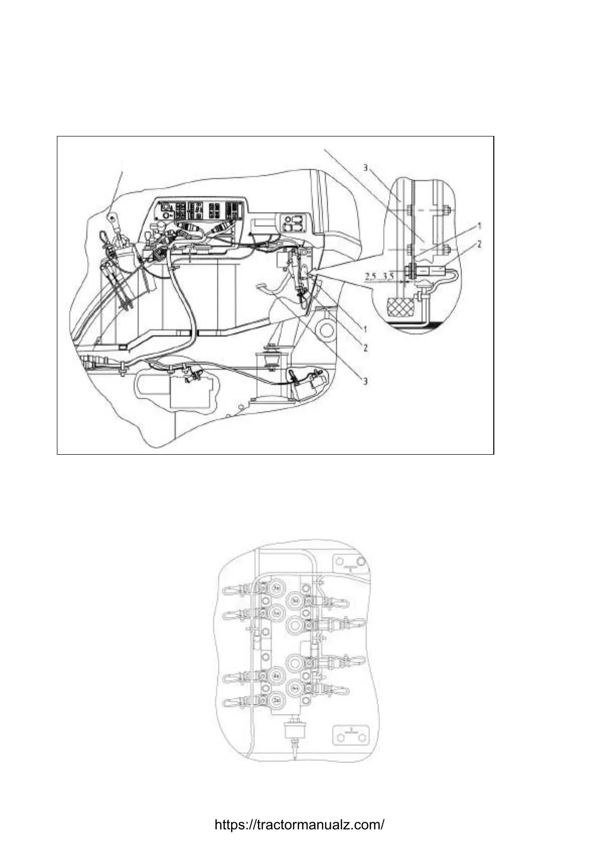
The sensor of clutch disengaged state on reverse 2 (figure 3.5.3) is adjusted by way
of turning the bracket 1 together with the sensor 2 in the slot in the bracket. The adjust-
ment shall be carried out with the engine running. After adjustment with the clutch fully
disengaged on reverse (the pedal is pressed against the stop), the square overlapping of
the sensor 2 end face by the pedal 3 shall make not less than 60%, the distance from the
sensor 1 end face to the clutch pedal 3 shall make 2,5 to 3,5 mm, as shown in figure 3.5.3.
1 – bracket; 2 – contactless position sensor; 3 – clutch pedal.
Figure 3.5.3 – Arrangement of sensor of clutch disengaged state on reverse
Connection of harnesses to electro-hydraulic distributors and pressure sensors,
mounted on the plate, is presented in figure 3.5.4.
Figure 3.5.4 – Plate with slave electro-hydraulic distributors and pressure sensors
https://tractormanualz.com/
 Loading...


