3522.5-0000010 РЭ
143
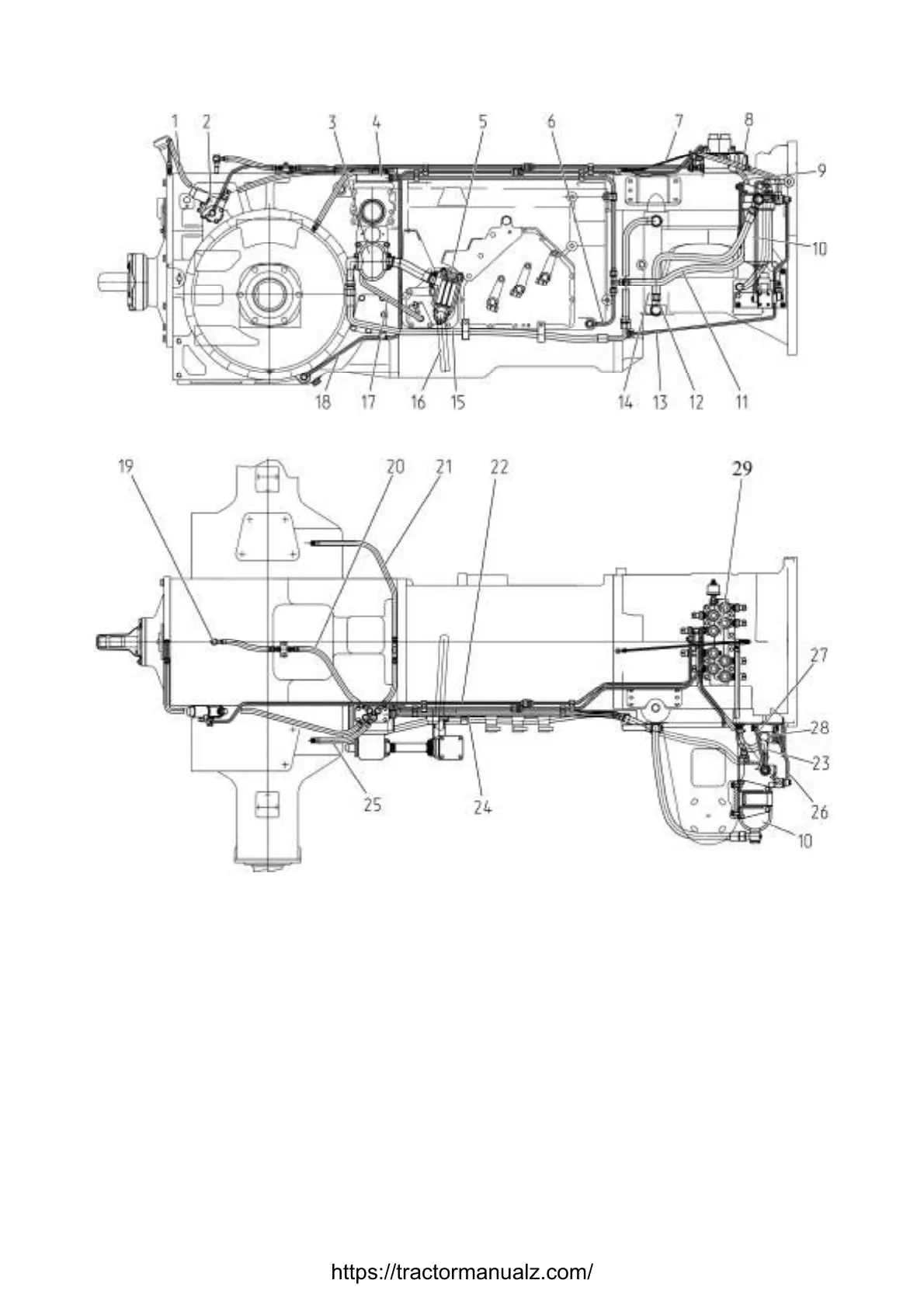
The location of transmission hydraulic system components is shown in figure 3.11.2.
а) view from the right
б) view from above
1 – rear PTO bearings lubrication line ; 2 – rear PTO control distributor; 3 – transmission hydrau-
lic system (HS) pump; 4 – distributing plate with an aperture for sprinkling of transmission HS
and HLL (hydraulic lift linkage) pumps drive; 5 – magnetic filter; 6 –line for GB bearings lubrica-
tion; 7 –line for gear shift group top bearing lubrication; 8 – line from duplex filter to electrohy-
draulic distributor; 9 –line for gear shift group bearings lubrication; 10 – duplex filter; 11 –line for
GB and rear axle lubrication; 12 – line from mesh filter to duplex filter; 13 – line for FDA en-
gagement; 14 – mesh filter (inside of clutch case); 15 – line from transmission HS pump to ele-
ments of transmission HS; 16 – suction bell (inside of gear box ); 17 – line from pumps drive
casing to drain; 18 – line for differential lock engagement; 19 – rear PTO sprinkling; 20 –line for
rear axle differential sprinkling; 21 – line for left final drive sprinkling; 22 – line from electrohy-
draulic distributor to rear PTO control distributor; 23 –drain after lubrication valve; 24 – line from
T-piece to plate; 25 – line for right final drive sprinkling; 26 – line from duplex filter to distributor;
27 –drain after the distributor; 28 – FDA control distributor ; 29 –electrohydraulic distributor.
Figure 3.11.2 – Location of transmission hydraulic system components
https://tractormanualz.com/