3522.5-0000010 РЭ
37
Table 2.2 – Correspondence of parameters of the indicator 3 (figure 2.7.1) to the
speed of the rear PTO end extension
Active annunciator of ranges of the rear PTO speed scale
Annunciator 6 “540 min
-1
”
1)
Annunciator 10 “1000min
-1
”
Upper (as per fig. 2.7.1)
active segment of the
rear PTO speed scale
650 1150 4
580 1050 5
500 950 7
420 850 8
320 750
2)
9
___________________________________________________________________________________________________________
1)
the annunciator of the range of “540 min
-1
” of the rear PTO speed scale is actu-
ated only if there is a signal from the sensor, and switches off when the annunciator of
the range of “1000 min
-1
” of the rear PTO speed scale turns on or when the signal from
the sensor is missing for more than 3 sec.
2)
speed value, whereby the annunciator of the range of “1000 min
-1
PTO speed scale turns on.
The working order of the rear PTO speed indicator 6 when switching on a mode
“1000min
-1
economy» is the same as for the mode of “1000 min
-1
”.
Note – A precise value of the rear PTO speed can be seen on the multifunctional
display 17 (figure 2.7.1).
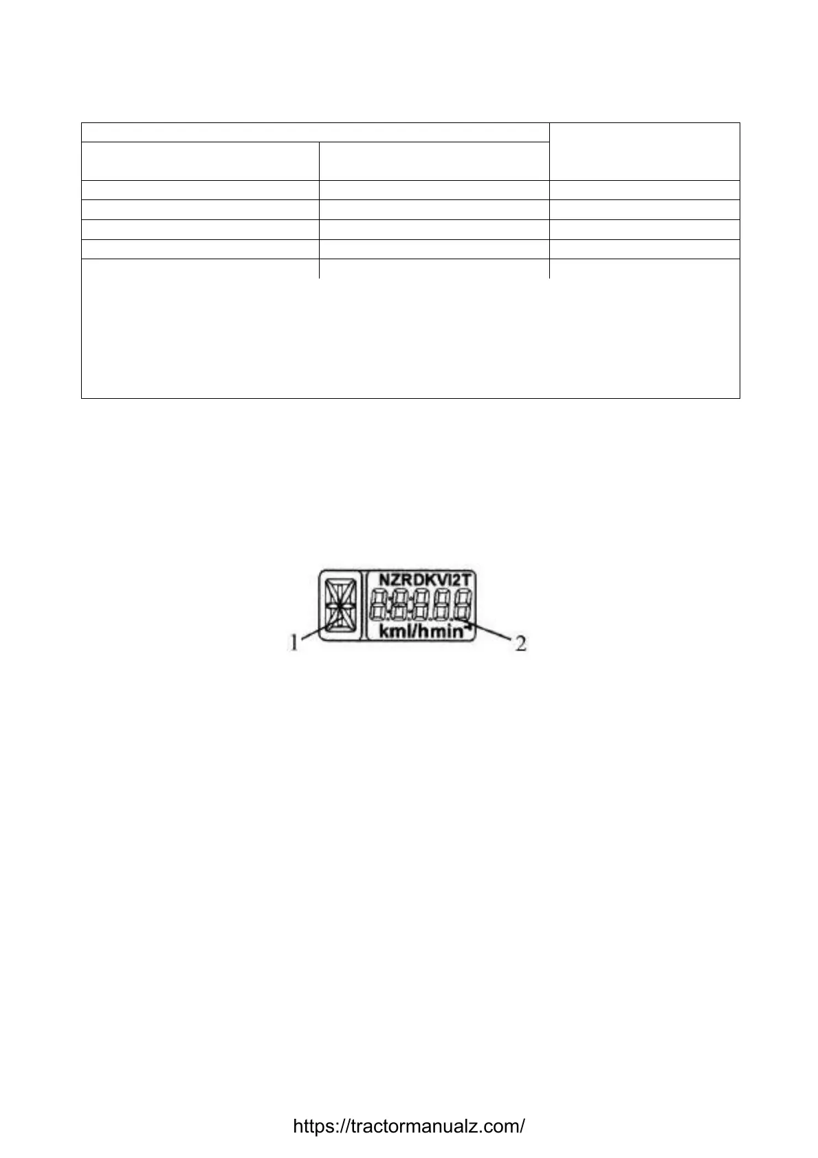
2.7.2.4 The multifunctional display 17 (figure 2.7.1) is a liquid-crystal display that
shows information in two fields 1 and 2 simultaneously (figure 2.7.3).
1 – digital symbol of the gear engaged (digits from 0 to 6); 2 – current numeric value
of one of tractor system parameters.
Figure 2.7.3 – Information fields of the multifunctional display
The multifunctional display receives information on the gear engaged from the
transmission control unit in the complex electronic control system CECS. This parameter is
displayed in the information field 1. In case the signal from CECS is missing (CECS fault,
wire breakage, loss of electrical contact, etc.), letter “A” is displayed in the information field
1.
The following parameters are displayed in the information field 1 (figure 2.7.3):
- total elapsed engine time;
- instant fuel flow;
- on-board voltage;
- remaining fuel volume;
- time of running with remaining fuel;
- rear PTO speed;
- testing workability of speed sensors;
- testing workability of frequency fuel volume sensor (FFVS);
- testing workability and connection of CAN-bus to the Integrated Indicator.
Switching between indication modes of “Total elapsed engine time “, “Instant fuel
flow”, “Remaining fuel volume”, “Time of running with remaining fuel”, “On-board voltage”,
https://tractormanualz.com/
 Loading...


