SPV26
11
English
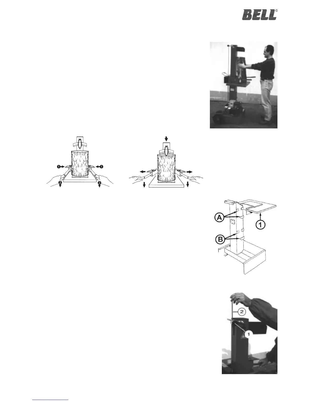
5.3 - Movable work surface
The movable work surface (1 in fig.12) allows the log capacity adjustment in relation to the log lenght.
The plane placed in A position allows to split logs until 72 cm. lenght. With the plane placed in B
position the logs lenght increases until 105 cm., but only until the wedge stroke.
5.2 How to use log splitter
· Place the log on the work surface as shown in fig.10 making sure it is centered under the
wedge. The two faces of the log must be parallel to each other and to the work surface to
guarantee safe operation.
· Working in the mandatory position only (fig. 1 page 3), grasp the log with the levers of the
ZHB control so that the jaws penetrate slightly into the bark and then lower the levers (fig.11/a);
the wedge will start to cut into the log.
Note: As soon as the wedge starts to split the log, widen the arms of the ZHB control slightly
(fig.11/b) continuing to press the levers down so that the force applied does not damage the
jaws.
· If the log does not split quickly or if the wedge stops, do not keep the machine under force.
Then hydraulic oil overheats very quickly with damage to the pump. It is advisable to return the
mast to the idle position and to make another attempt after rotating the log.
· Repeat the operation with the pieces obtained so as to split the log into several parts.
Note: If you let go of even just one of the levers, the machine will stop in the position reached. If
you let go of both levers, the telescopic mast will move to the fully open position.
Fig.10 Positioning of the log
on the log splitter
Fig.11/b Two-hand controlFig.11/a Two-hand control
5.4 - How to adjust blade stroke
To save time, a system has been designed that makes it possible to adjust wedge travel so that this
can be set for short logs. In this way, the wedge travels for the distance required only.
After checking the length of the longest logs to be split, regulate wedge travel as follows:
· Start the log splitter and bring the wedge to the position required. Release one of machine
control levers so that the wedge stops in the selected position.
· Back off knob 1 in fig. 13 with the other hand.
· Pull the rod (2) up until it locks in place.
· Draw up the knob (1) again making sure it is tight.
The log splitter will now reposition at the point selected.
Fig.13 Blade travel adjustment
Fig.12 Movable work surface