SPV26
16
English
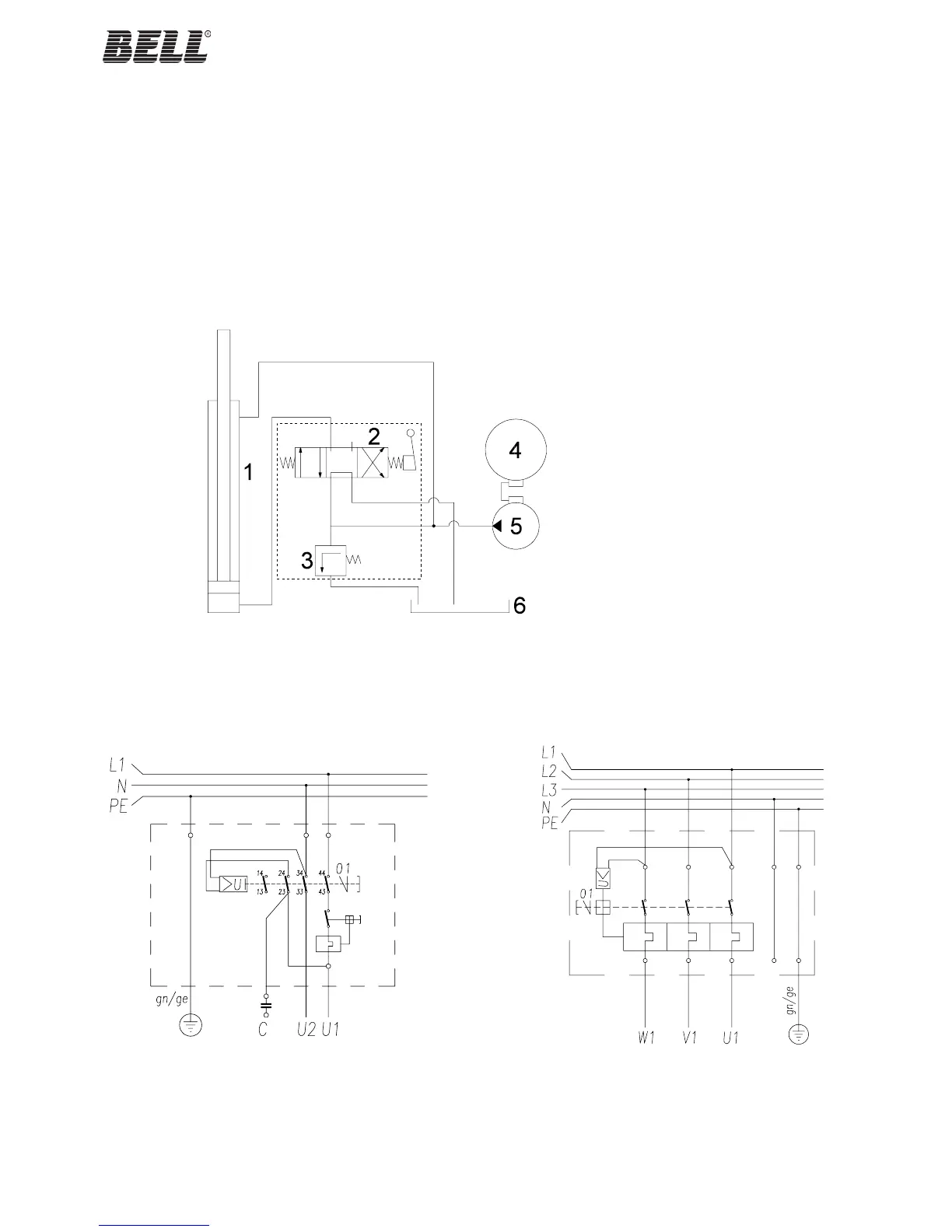
HYDRAULIC DIAGRAM
1 Cylinder
2 Control valve
3 Max. pressure valve
4 Motor
5 Pump (2cm
3
/round)
6 Tank
THREE-PHASE ELECTRIC DIAGRAMSINGLE-PHASE ELECTRIC DIAGRAM
APPENDIX A - WIRING AND HYDRAULIC DIAGRAMS
I WARNING
The following is reserved solely for the authorised personnel of the retailer.
The manufacturer declines any responsibility for damage or injury of any kind ensuing to persons, animals or objects due to
improper or unauthorised use of this documentation.
 Loading...